This thread has been locked.

If you have a related question, please click the "Ask a related question" button in the top right corner. The newly created question will be automatically linked to this question.

LMX2571 pedestal noise reduction

Other Parts Discussed in Thread: LMX2571, CODELOADER

Hello,

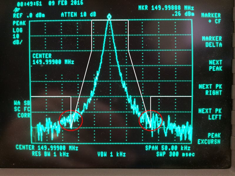
We're using the LMX2571 as a synthesizer for an FCC Part 90 application and for the most part, it's working well.  However, we have noise that we need to reduce.   In my photo, I've marked FCC Emission Mask D in white and circled the emission area of concern in red.  This spectrograph was generated using the TI EVM board and loaded using CodeLoader (nice tool, by the way).  Modulation was turned off.  We get very similar results using the board we designed using the LMX2571.  Our TCXO, is a Connor Winfield DV75D TCXO with jitter < 1ps (like the EVM).  Our loop filter design on pin 25 (CPout) is the same as that used on the EVM board.  

What is likely to be the source of this noise?  Loop filter? VCO noise? Is 1ps jitter too high?

We have adjusted the phase detector frequency up from our original 10mHz value but there was no noticeable noise reduction.  We have also adjusted the internal LFR3, and LFR4 values as well as the charge pump current and gain, still with no reduction in noise.    If I need to change the LF bandwidth, I would very much appreciate help in selecting values or a pointer to app notes that specifically call out the math for component selection.

Thanks!

Steve

  • Hi Steve,

    We received your message. We will get back to you shortly.

    Thanks,
    Julian
  • Hi Julian,

    Thanks.  This is an urgent issue for us.

    Steve

  • Steve,

    I would encourage you to try our Clock Architect (WebBench) tool or the offline Clock design tool;  these simulate phase noise along with showing the contributions of each block (PLL, VCO,..) at each offset.

    This question is very specific to the loop bandwidth.

    For our evaluation board, the loop bandwidth is very wide and all the noise would be inside the loop bandwidth.  For offsets below 1-2 kHz, this would likely be the XO.  For offsets from 10-100 kHz, this could be  the 1/f noise of the PLL, which would not improve for higher phase detector.  Outside the loop bandwidth, it is mostly VCO.   I would not expect too much noise contribution from the loop itself except maybe a little near the loop bandwidth of the PLL.

    Regards,

    Dean

  • Hi Steve,

    From the spectral mask, it looks to me that your phase noise requirement at 12.5kHz offset is -100dBc/Hz. With the default EVM configuration, you should get better than -130dBc/Hz. Even if you change the phase detector frequency to 10MHz, the phase noise is already better than -110dBc/Hz. I think the reason that you did not get these number is because of the LO of the spectrum analyzer that you are using has phase noise higher than our device. if you are able to use a newer spectrum analyzer, I am sure you can get better test result. FYI, below is my test data at different phase detector frequencies.

  • Hi Dean,

    Thanks you for the fast replay.  I'll take a look at Clock Architect. 

    Is there a tool or app note specific to calculating component values for the loop filter?  I haven't found anything in the LMX2571 datasheet or other sources specific to that part for determining BW.  For our design we chose filter components on CPout (pin25) to be the same as the eval board and it seems to work well, but optimizing this might be good for noise, stability, etc.

    Thanks again for your help!

    Steve

  • Hi Noel,

    Thanks for putting an EVM on test to help us find this problem. From your suggestion, we put two commercially produced transmitters on our HP spectrum analyzer and saw similar results to that of the LMX2571 EVM, so we are now suspicious of the test equipment. We're going to test the EVM and our board on newer, higher end equipment.

    Thanks again for the fast, thoughtful response.

    Steve