This thread has been locked.

If you have a related question, please click the "Ask a related question" button in the top right corner. The newly created question will be automatically linked to this question.

LMK61E2-xxx

Other Parts Discussed in Thread: LMK61E2

Hello,


I have been trying to use the LMK61E2-125 clock source for driving a high speed DAC (AD9106).

Apparently, it should be a breeze getting the clock up and running, seeing as essentially only a stable supply voltage (3.3V), solid GND plane and a pull-up resistor for OE is needed. (Well, technically OE is supposed to have internal pull-up, but I added an external 10k resistor just to be sure).

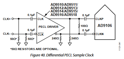
Below the suggested driver configuration of the DAC is shown, using a PECL signal. I use the LMK61E2-125 as a substitute for the "AD9510/..."-driver.

I realize that the datasheet for the LMK suggests 150R resistors to GND, but the ~100R difference should not be detrimental to functionality, right?

So supposedly everything should be in working order - although not perfectly tuned. But when I turn on power, I only get ~1.5V DC on the output pins. (Yes, this is measured with a single-ended probe, as I currently haven't got access to fancy stuff like differential probes; I just need an indication of something actually working).

So I have tried removing the 100R resistor between the outputs - no luck.

Moving it past the DC-blocking caps - no luck.

I'm sorta running out of ideas, as there are not a whole lot of configuration options here....

Does anyone out there have an idea of what has gone wrong? Or seen this (lack of) behaviour before?

For good measure I should mention that the chip is handsoldered - I enlarged the PCB footprint to accommodate a soldering iron in order to mount the IC.

  • Did you check the current draw on the supply node of LMK61E2? For LVPECL, the typ current would be around 160mA.

    If you don't see any current, please measure the DC voltage at the VDD pad of LMK61E2 to ensure that at least 3.135V is present. If not, there is a loss somewhere on your power network. Likely due to higher DCR of any ferrite beads on the supply node.

    If these are ok, then we need to look at whether any issue happened from violating the recommended reflow profile. J-STD-020 must be followed and I am wondering whether hand-soldering caused violation of this spec. This will likely result in device malfunction. Can you use the profile as a guidance and try again? 

  • Thank you for the reply.


    Yes, the current draw is very low, ~10mA in fact. Although it seems clear that the IC cannot run with any output at this current, it does seem to suggest that something is actually consuming power.

    On a related note the supply voltage is very close to 3.3V on the trace for the IC supply pin.

    Are these device extremely sensitive to the soldering profile used? Because I did try to be careful during soldering, and not use too much heat or time on any pins (unfortunately I cannot give exact details on heat or duration while soldering, as I really do not remember exactly).
    With regard to ESD, how are these devices? I mean, obviously they are sensitive, but are they like "we couldn't fit ESD-protection into the package and everything is high impedance"-sensitive?

    If I am to give it another try, I have to use the adjustable version "LMK61A2" instead, as these are the only replacements I have in stock. But before I tear open the IC packaging, is there anything else that I should be aware of (except maybe moisture levels)? And if I use the adjustable version of the LMK61, is there a quick'n'dirty way to get it up and running, to verify that the mounting went well?

  • The ESD on each pin is 2kV HBM and 500V CDM. So this shouldn't be an issue.

    We require that J-STD-020 be followed for the reflow profile.

    For your rework on LMK61A2, it is LVDS outputs and so please remove the 150 ohm to GND on each P and N of output. When you power up, the current draw should be around 150mA. If this happens, you should be good. 

  • Thank you very much for the reply!
    I know it has been a while, but I had some other business to take care of as well...

    After trying to get a reflow oven to do my bidding, without success unfortunately, I did some rework on the PCB and made i extremely soldering friendly, at the cost of some GND plane. Taking all possible precautions I mounted a newly delivered IC (fixed frequency) on the board using a 'hot air gun' (whatever they are called) and a microscope to check my solderings. Although extremely time-consuming it, I was able to debug the circuit by your advice (current draw) and get everything up and running!

    So to sum up;
    great IC (wan't wait to measure supply ripple and clock jitter), but very, very fragile when soldered!
    Next major step; see if the adustable-frequency version will play ball :-)

    Oh, and by the way, for anyone having trouble with this IC; make sure your decoupling and/or bypass network is sufficient/oversized for testing.
    I use 10u, 1u and 100nF after a 470R@100MHz supply ferrite bead.

    Thank you again for your time and advise!