This thread has been locked.

If you have a related question, please click the "Ask a related question" button in the top right corner. The newly created question will be automatically linked to this question.

CDCM6208V2 Evaluation Board PLL Lock time

Other Parts Discussed in Thread: CDCM6208

Hello,

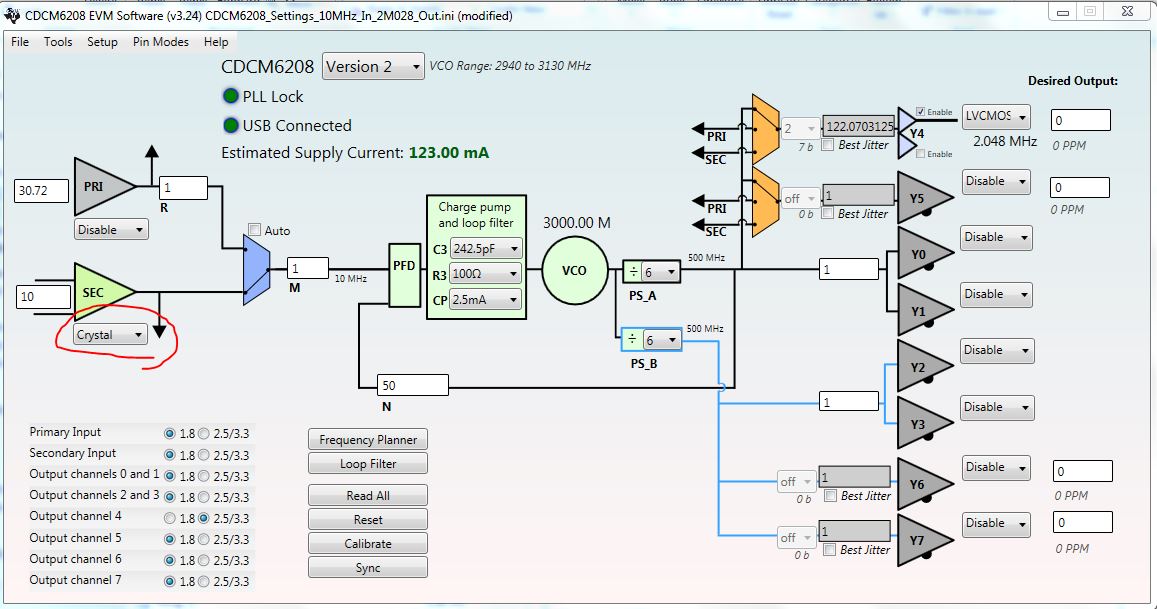
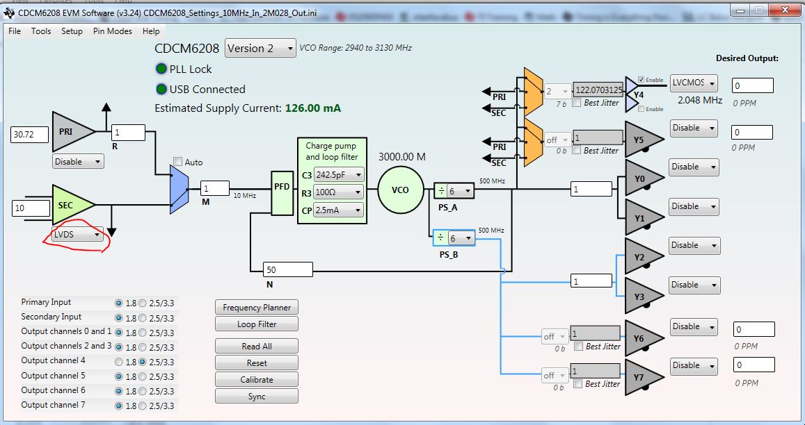
I am using a CDCM6208V2 Evaluation Board to get a 2.048 MHz clock signal from a 10 MHz sine wave signal.
I use the board in bootloader mode with my configuration.
Sometimes it works quick : the PLL is locked after a few seconds and I have my output signal. Sometimes it works but I have to wait a long time to have my output signal (few minutes). And sometimes it seems not to work at all because the PLL never locks or it is way too long and I have no output signal.

It bothers me because I don't understand how sometimes it works this way and sometimes it works another.

I would like to know why this happens and maybe obtain an every-time working method.
Thanks you for your answers.

Kind regards,
Simon

  • Hello Simon,

    could you please share your register settings and also which loop filter option you use on the eval board?
    it might be that the Loop filter is not configured well and the loop has too little phase margin. You can check the phase margin (PM) when you click on "loop filter" button in the software. As soon you entered the External loop filter components C1, C2, R2 you can click on "Calculate Output (Using RC input)". The PM should be ideally around 60-70.

    Best regards,
    Julian
  • Hi Julian,

    Here is my register configuration :

    Register 0: 01B9
    Register 1: 0000
    Register 2: 0031
    Register 3: 00FA
    Register 4: 30E0
    Register 5: 0000
    Register 6: 0000
    Register 7: 0000
    Register 8: 0000
    Register 9: 0253
    Register 10: 0791
    Register 11: 2000
    Register 12: 0000
    Register 13: 0000
    Register 14: 0000
    Register 15: 0000
    Register 16: 0000
    Register 17: 0000
    Register 18: 0000
    Register 19: 0000
    Register 20: 0000
    Register 21: 0000
    Register 40: 0000

    I use the filter configuration 1 on the board but I plan to use my own filter outside of the eval board, calculated by a filter design tool. Which one would you advise me to use at the moment ?

    Thank you for your help.

    Simon

  • Hi Simon,

    CDCM6208_Settings_10MHz_In_2M028_Out.zip

    I input your registers into CDCM6208 EVM software, this software also could save your configuration as .ini document, as my attachment.

    The problem could be from 10MHz sine wave input. In your setting, it is Crystal mode.

    How about 10MHz sine wave amplitude? AC coupling or DC coupling? Is there DC bias with the sine wave?

    Could you show your schematic about this input circuit?

    Best Regards,

    Shawn

  • Hi Shawn,

    My input signal is a sine wave 10 MHz AC coupled -0.6 V / +0.6 V because of the input capacitor. I can display it from the SEC_REF pin of the CDCM6208.

    Kind regards,

    Simon

  • Hi Simon,

    We should change input type to LVDS in register setting. If the 10MHz source could drive 50 Ohm load, then below schematic could work. I also highlight input requirement from datasheet. .ini also is attached. Please refer.

    https://e2e.ti.com/cfs-file/__key/communityserver-discussions-components-files/48/CDCM6208_5F00_Settings_5F00_10MHz_5F00_In_5F00_LVDS_5F00_2M028_5F00_Out.ini

    Best Regards,

    Shawn

  • Hi Shawn,

    I got your idea and I tried something similar with what was available. I included a 1.2 Vpp to 1 Vpp conversion circuit with 10 Ω and 50 Ω resistors (I didn't understand the use of the 500 Ω resistor). I also connected SEC_REFN with R89. I put JMP11 on 0p9V. I changed R4[7:6] to LVDS mode.

    Shouldn't this work as well? I don't understand why I have a sine wave on SEC_REFN. The PLL doesn't lock and I get 1.93 MHz in output.

    Thanks.

    Kind regards,

    Simon

  • Hi Simon,
    500 Ohm is to make PI resistors network (500, 10,45.3) equal to 50Ohm , looked from transmission line. How about R72, R73? They should be DNI. How about 0.9V waveform?

    Best Regards
    Shawn