This thread has been locked.

If you have a related question, please click the "Ask a related question" button in the top right corner. The newly created question will be automatically linked to this question.

CDCLVC1102 clock buffer is generating 125MHz with rise and fall time delay

HI,

We are using a clock buffer (PN: CDCLVC1102PW)  with operating voltage 2.5V and input clock assigned 125MHz from clock synthesizer(PN: XR81101) output. as per datasheet output parameter rise and fall time should be 0.3ns to 1.2ns.

but, observed that,

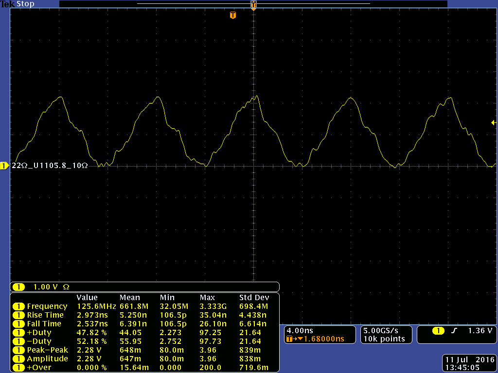
first, I captured waveform at clock buffer input terminal and parameters are with in specified range only. second, I captured waveform at buffer output and looks rise and fall parameters are changed a lot compared with datasheet parameter.

Oscilloscope bandwidth is 1GHz and sampling rate is 4GSps and differential probe I used and bandwidth is 1.5GHZ

Please see captured waveform and schematic and help on this issue and need to solve immediately.


  • There appears to be clock signal integrity issue / reflections which could be due to impedance mismatch.
    Is your PCB trace using 50 ohm controlled impedance? Are there any vias which could add impedance discontinities?
    Did you use series resistor of 0 ohms for VDD=2.5V per Figure 7 in the datasheet? Note that the driver output impdance is matched already to 50 ohms trace when VDD=2.5V.

    Alan