This thread has been locked.

If you have a related question, please click the "Ask a related question" button in the top right corner. The newly created question will be automatically linked to this question.

CDCM7005 not locking

Other Parts Discussed in Thread: CDCM7005

Hello,

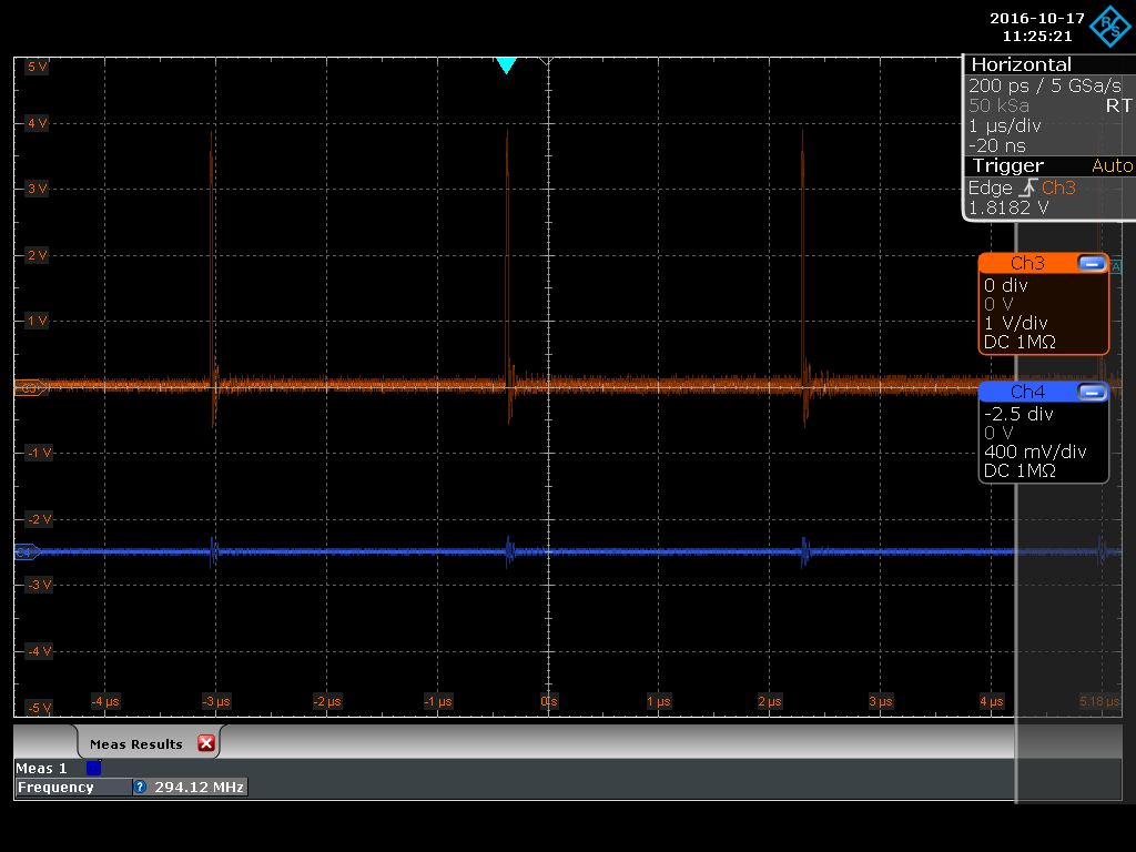
I am unable to have a lock on the clock while having a reference 48Mhz clock and a 48Mhz output.

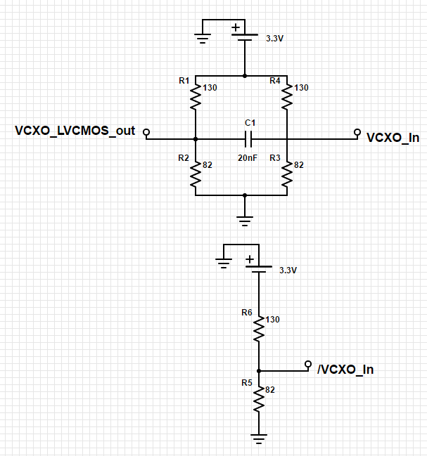
I am using the passive loop capacitors and resistor values that are given as example in the datasheet.

The values that I used in the PLL are the ones shown bellow: 

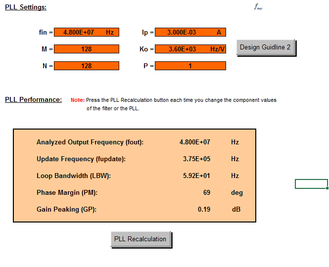
LBW seems a bit low but my guess is that shouldn't be a problem. 

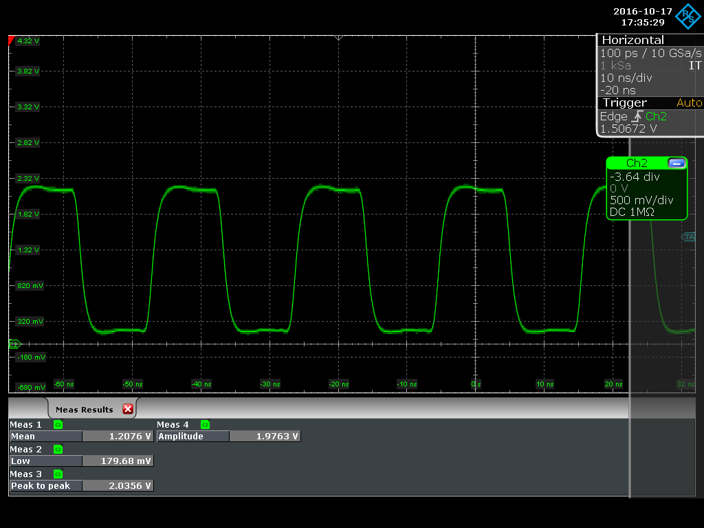
I am using the a 48Mhz VCXO with:

Control Voltage Tuning Slope - 40 ~ 75 ppm/V

BW - 10 kHz

The settings that I am using for the CDCM7005 configuration are the following:

word 0: 0x4007F1FC

word 1: 0x28000001

word 2: 0x500000F2

word 3: 0x0000024B

PS: Although I am using analog lock, I have already tested digital lock and no changes were observed.

  • Hello Tiago,
    can you please let me know if you use the TI EVM or if you have your own test board?
    Is the VCXO LVPECL and the reference clock LVCMOS?
    Are the jumpers for the control voltage set and the loop filter passives connected? (J32, J33)
    Can you please try word 3 using 0x1001004B?
    You will be able to observe the signals at the PFD input on the status pins (status_ref = Pri_ref or sec_ref / M; status_vcxo=vcxo_in / P / N).

    Please let me know if you see stable clock signals.

    Best regards,
    Patrick
  • Hello Patrick,

    I am using our prototype board.

    Both VCXO and reference clock are LVCMOS.

    I believe the jumpers your are referring to are from the EVM board, not applicable here.

    I've used the word3 value you sugested and was very confused with the results. I'm assuming these were not to be expected. Since the input signals are 48 Mhz clocks (I have checked it as I had done before in light of these results). Thank you for your support.

    Ch3 (orange): STATUS REF

    Ch4 (blue): VCXO STATUS

  • Hello Tiago,

    thank you for sharing this.

    The result is partially expected. We observe here the signals at the PFD. On the reference path (CH3) we have roughly 375 kHz which is your 48 MHz / reference divider M(=128). The VCXO input does not see a proper clock signal yet. It is not toggling at all, only some cross-talk through the probing can be seen.

    Is the LVCMOS source only connected to VCXO_IN and !VCXO_IN is most likely floating. Please apply a differential signal or pull the !VCXO_IN pin to the threshhold level and reduce the swing on the VCXO_IN. When you already have some single ended to differential scheme on the prototype board, please cross-check the levels again. You can use a static differential logic high or logic low, too. Then you should see that the VCXO signal goes through to the PFD and you can lock the PLL.

    Best regards,

    Patrick

  • Hello again Patrick,

    The only thing that I seemed to be missing from what you said was the reduced swing voltage. I have found other topic on the e2e forum that said it had to be below 2V. I have done this using the following circuit:

    The input VCXO input on the CDC is the following:

    I would expect a change in the diagnostics VCXO input signal but I have seen none. Is there still something other detail that I failed to address?

    Thanks again for your great support.

  • Hello Tiago,
    thanks for sharing that measurement!
    One thing I forgot to ask - do you see the output toggling or is it only the PLL path not locking?
    I assume the outputs are not toggling from above scope shot from the status pin.
    How much current does the part consume when you release reset (no re-programming yet)?

    Thanks!

    Best regards,
    Patrick
  • Hello again Patrick.

    The outputs are toggling at the correct frequency although there is no lock. I have no way to tell how much the part is consuming.

    However I have tested the Lock Window with Cycle slip and I have lock although not stable. I have yet to see the outputs locked with the input clock.

    Thanks!

    Best regards,

    Tiago