This thread has been locked.

If you have a related question, please click the "Ask a related question" button in the top right corner. The newly created question will be automatically linked to this question.

LMK03328 / generate a 74.17582418MHz output register file

Other Parts Discussed in Thread: CODELOADER

HI TI,  I'd like to make a 74.17582418MHz output from 25MHz input.

I did simulation with Webench and the PLL setup is as below.

---------------------------------------------------

Name Design Value
Filter Type Passive
Filter Order 3rd Order
Op Amp Gain 1.00
Charge Pump Gain 6.40 mA
VCO Gain 45.00 MHz/V
VCO Input Capacitance 0.00 pF
VCO Frequency 4821.429 MHz
Phase Det. Frequency 25.00 MHz
Filter type designed
Brickwall Bandwidth 287.4542197221997 kHz
Delta Sigma Order 3
Randomization Factor 0.0 %
PLL Whole Part 192
PLL Numerator 267857.0
PLL Denominator 312500.0
Reference spurs enabled
Fractional spurs disabled
Subfractional spurs disabled
Other spurs enabled 

I tried to make a setup file by CodeLoader but I could not make a 74.17582418MHz output as below,  

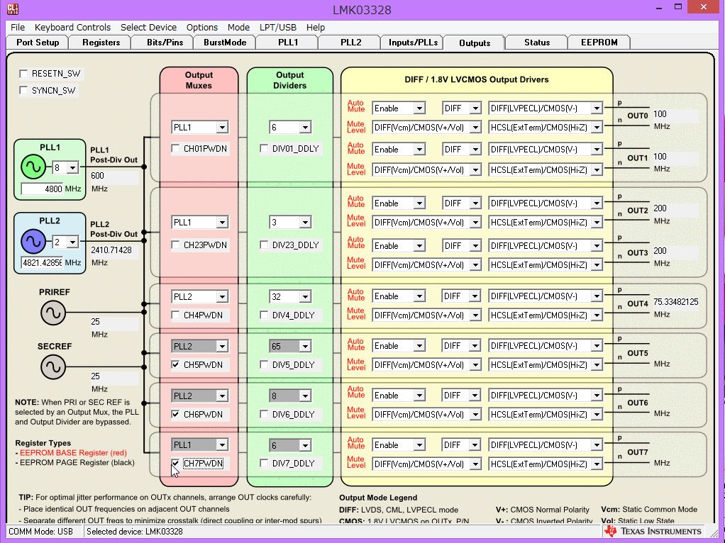
In order to make a 74.17582418MHz,    I should make  a  "4821.429 MHz divide by 65"  circuit . but the device could not the circuit because  the device has "/2, /3,/4,,,," divider after the PLL.

Any way, Please let me know how to generate a register setup file  "25MHz input, 74.17582418MHz output "  by CodeLoader ?


  • Hi Toshi,

    You can divide the VCO frequency by 65 by first setting the PLL post divider to 5 and then the channel output divider to 13. This gives a total divide factor of 65. Note that due to the limitations of the fractional PLL feedback divider, you may not be able to achieve exactly that output frequency from a 25MHz input, but you can get very close.

    Regards,
    -Tim
  • Tim-san, thank you very much for your Help. 

     I can make a register setup file by using CodeLoader.  

    The close frequency should be 74.175824MHz, correct ?

  • Hi Toshi-san,

    Webench is useful for simulating output phase noise but sometimes rounds long fractions excessively.


    You can achieve a closer output frequency of 74.17582417582... with the configuration described below:

    -To get as close as possible to 74.17582418 MHz, the VCO frequency should be as close as possible to 74.17582418 x 65, or 4821.4285717 MHz.
    -The input frequency is 25 MHz. Enabling the doubler (for higher performance), yields a phase detector frequency of 50 MHz.
    -Therefore, the PLL feedback divider (N) should be as close as possible to 4821.4285717 / 50, or 96.428571434. The integer portion of the divider will be 96.
    -The maximum numerator/denominator of the fractional portion of the feedback divider is 4194303 (2^22 values). Therefore we must find the fraction with denominator less than 4194303 that most closely approximates 0.428571434. This fraction is 3/7.
    -Setting the divider to 96 and 3/7 yields a VCO frequency of 4821.42857142857. If we divide that by 65, we obtain our output frequency of 74.17582417582...

    Regards,
    -Tim