Hello,
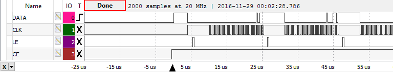
I am using the LMX2541 to generate a signal with a center frequency of 978 MHz. The deviation is 312.5kHz. However, I am having trouble getting it to properly start. To ensure that the device is being programmed, I have been checking the Ftest/LD pin, which I have set in the registers to go high once it is programmed. However, it is always low, and no signal seems to come from the RFout pin, leading me to believe that the device is not being programmed. I am using the SPI bus of an MSP430. I have attached my register values below, as well as a timing diagram take from a logic analyzer:
0x00,0x00,0x00,0x17, //R7
0x00,0x00,0x00,0x1C, //R12
0x28,0x00,0x14,0x09, //R9
0x01,0x11,0xCE,0x58, //R8
0x00,0x1F,0x33,0x26, //R6
0xA0,0x00,0x00,0x05, //R5
0x88,0x04,0x41,0x94, //R4
0x80,0x24,0x2F,0x03, //R3
0x04,0x00,0x06,0x42, //R2
0x00,0x00,0x00,0x21, //R1
0x50,0x30,0x09,0xC0, //R0
0x88,0x04,0x41,0x94 //R4, due to divisor value of 4

1) Does anything in the timing of the serial data appear to be incorrect? Additionally, will the gaps in between transmission of each byte over SPI cause issues (the SPI TX buffer is one byte in length)?
2) What is the default condition of the Ftest pin?
3) What is the best way to ensure that the chip is properly powered up before programming it? What voltages should I be able to measure?
Thanks,
Calvin