This thread has been locked.

If you have a related question, please click the "Ask a related question" button in the top right corner. The newly created question will be automatically linked to this question.

sync multiple lmk0482x through PLL2

Other Parts Discussed in Thread: LMK04828

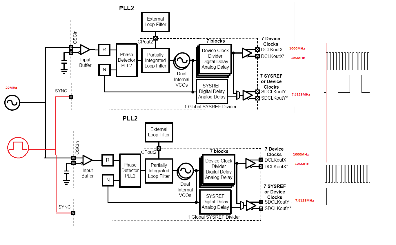
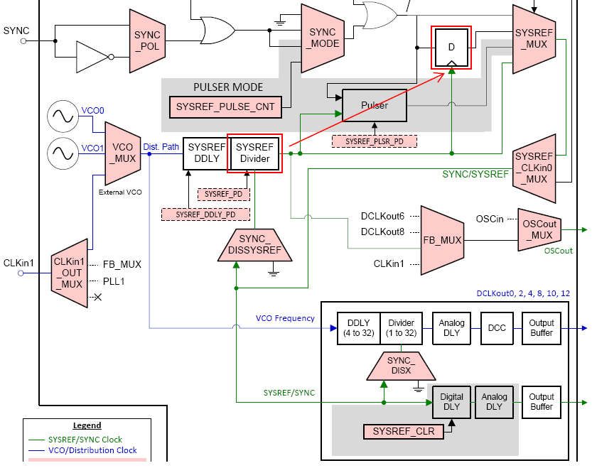
I would like to sync multiple LMK04828's outputs on separate boards, a reference 20MHz is fan-out to each OSCin of LMK04828, Can a common external SYNC signal synchronize all outputs??? can external input SYNC synchronize  multiple LMK04828's output dividers??? what the phase relationship between OSCin and SYNC input???

  • the SYNC input is reclocked by the 'SYSREF Divider',if using normal PLL2 mode,SYSREF Divider have 384 phase possibility (VCO=3000,SYSREF output =7.8125,3000/7.8125=384) ?

    Basic Sync Mode seems to be working:SYNC_MODE = 1, SYSREF_MUX = 0,CLKin0_OUT_MUX != 0.

    Both SYSREF_Divider and SDCLK_Divider are reset by the same SYNC edge,since  VCO phase is fixed with the reference input phase ,The VCO phase of the multi LMK04828 is always aligned in integer mode,right? same SYNC edge will trigger all the LMK04828's SDCLK/DCLK Devider,synchronization done! 

    SYNC input edge skew seen by each LMK should be less than a VCO period,otherwise LMKs output phase is differ with integer number of VCO period.

  • in 0-delay mode,SDCLKout must be an integer multiple of OSCin frequency!?
  • Hello Min Hu,

    Using the SYNC input to reset the dividers directly, you will be required to meet some timing to the VCO. Since you won't know the exact phase of the VCO (there is some variation over PVT from the reference input to VCO in part due to the phase detector phase varation) you may not always be able to achieve +/- 0 device clock error between your two LMK devices.
    > If you provide a SYNC signal into CLKin0 and route CLKin0 to the SYNC/SYSREF bus, that is a high performance path which will improve your chances/remove the variation. But if you need +/- 0 deterministic error I'll suggest two methods:
    1) Use the SYSREF (or lower) frequency as a reference. Because the SYSREF frequency is relatively low... You'll probably want to run dual loop to use a VCXO to provide a clean and relatively high (100 MHz) reference to PLL2. This allows PLL2 to operate with low noise and both devices will have SYSREF in phase because you will also use SYSREF divider for 0-delay feedback.

    2) The other option is to place the SYSREF divider in 0-delay to PLL2 N. Instead of programming SYSREF divider for SYSREF frequency, program the SYSREF divider for the reference frequency. Set the SYSREF_MUX to select the reclocked (D flip flop) input. Now if you provide a SYNC signal (I always recommend CLKin0 for SYNC input because it's a high speed path), you don't have to meet timing against the VCO frequency anymore, but the much lower frequency of the reference frequency. This will allow you to reset the other dividers deterministically or re-clock a SYSREF to the output.
    - This LMK device will not be able to generate a low frequency SYSREF anymore because the SYSREF divider is operating at a higher frequency. But you can program the other LMK04828 device in your system to generate a SYSREF and feed it into CLKin0. If you use HSDS 8 mA output, you can provide a DC connection into CLKin0 in Bipolar input mode. Provided both LMK devices receive a common reference, and both devices are in 0-delay mode. Phases will be aligned and you can SYNC the slave device and provide SYSREF to it's downstream JESD204B targets.

    73,
    Timothy


    73,
    Timothy