This thread has been locked.

If you have a related question, please click the "Ask a related question" button in the top right corner. The newly created question will be automatically linked to this question.

CDCE913 pullability - no hint that it's working....

Other Parts Discussed in Thread: CDCE913, CLOCKPRO

I'm developing a product that puts multiple devices on a shared bus, each with its own CDCE913 driving both the microcontroller and the ADC.  Bus commands provide sync pulses that tell me what the clocks are on the master and slave nodes, and I'll be feeding that into a PID with the goal of locking all the slave clocks to the master.

The CDCE913 has a 16.384MHz crystal (http://search.digikey.com/scripts/DkSearch/dksus.dll?Detail&name=535-9676-1-ND), with output Y1 divided by 4 to provide a 4.096MHz ADC clock, and the relevant settings to generate 8MHz output on Y2 to drive the microcontroller (which has its own PLL boost to 32MHz, though I should try running 32MHz extclk directly at some point).  The MCU has a DAC output through an attempt at a filter, straight into Vctrl.  The theory is that I should be able to take this 10ppm crystal and pull it a decent amount more than that, and the 12-bit DAC should provide enough resolution to have a reasonable lock between all the units on the bus.

However, I have been able to obtain no evidence that I'm able to alter the crystal speed in the slightest.  In fact, I've constructed a simple program that uses another microcontroller to count the clocks from two units at the same time, and the difference I'm seeing is more like 500ppm, with no visible effect from changing Vctrl across the entire range (0-1.8V).

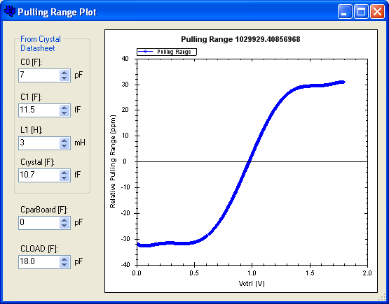
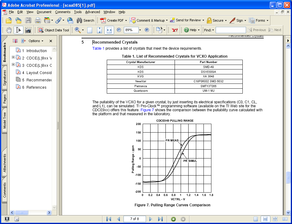
A major part of the problem is that the TI documentation on pullability refers to a number of crystal parameters that nobody else does (datasheets typically have ~2-3 parameters, TI wants ~4-5), so I have no idea how to calculate whether a given crystal (like the one above) is even remotely appropriate.  Regardless, I shouldn't be seeing 500ppm difference when the crystals are spec'd for 10ppm....

Any hints on what's going on?

  • In the datasheet of the XTAL you mentioned, the CL=18pF and the shunt capacitance is C0=7pF. +/-40ppm is the pulling range of the chosen XTAL calculated with the Pulling range tool included in the TI clock pro (http://www.ti.com/litv/zip/scac119).


    You can find recommended XTALs to use the CDCE913 as VCXO on page 7 of the following AN: http://www.ti.com/litv/pdf/scaa085

  • [caveat: I'm very much a digital guy, analog and me just don't click]

    OK, so that's a start on calculating the range, but where do I get C1, L1, and Ccrystal?  Of the many crystal datasheets I've looked at, I have never once seen any hint of them being listed.  Are they something I'm forced to measure somehow, and am I going to be able to do that with a basic 1GS scope, or is it something sufficiently intrinsic to a crystal that I don't really need to worry about it?  My experimentations with the plotter show that C1 changes are nearly 1:1 linear (meaning halving the value nearly halves the range), L1 doesn't show any difference even changing it to 5m, and Ccrystal has relatively little effect.

    As far as selecting a crystal from the table given, not a single one of them is available from any parts supplier I'm aware of.  Only a couple parts came up with listings at all via findchips.com, and those were both out of stock and from companies that sell quantity.  A list of suggestions that can actually be found at Digikey, Mouser, Newark, etc. would be far more useful.

    I'm still confused by a lot of scaa85 though.  For instance, it says "For the crystals (used for the VCXO application) to fulfill this requirement the ratio p = C0/C1 should be close to 220 (or even smaller)."  With the default values provided by ClockPro of C0=7pF and C1=11.5fF, I get a p=608, which is definitely not close to or smaller than 220.  The doc goes on to say "Having C1 > 20 pF also ensures better performances (pullability > 120 ppm)."  Claiming that C1 should be greater than 20pF seems to be insanity, since ClockPro sets a default value that's nearly 2000 time smaller (11.5*femto*Farad).  Should that instead read Cload?  Even so, putting a higher Cload into the plot gives a noticeably *smaller* range.

    Thus I'm confused.


    That still leaves the two main problems I'm having however:

    First, the absolute out-of-box accuracy is wildly off.  500-800ppm is definitely not 10.  Is this perhaps due to the default 10pF listed as Crystal Load in ClockPro, and that I need to change it to the 18pF from the datasheet?  Will that change the on-chip loading to a value that lets the crystal oscillate at a higher accuracy?  Although I need to account for the extra 10pF load caps I have on the PCB as well.  Does that mean I add 5pF to the crystal's 18, and put 23pF into the plot?

    Second, I don't see any measurable change when I move Vctrl.  Perhaps once I solve the first problem and get them far closer together I'll be able to enhance my test-bench resolution and actually see something in the ~100ppm range.

  • Dear Mr. Walthinsen,


    thank to your feedback we were able to spot a typo into the application note scaa085.

    C1 must be actually bigger than 20 femto Farad and not pico Farad. This will be corrected in pag.4.

    If you need to "pull" your frequency of a certain amount of ppm, you will need to choose the appropriate crystal. Most of the standard off the shelf crystals are not pullable or shlightly pullable, therefore you need to request by crystal manufacturers crystals that have high pullability (few of them are listed in the apps note you read at pag.5.

    Along with your request, you can ask them to provide you with a sheet where Lm (motional inductance ca;;ed L1), Cm (motional capacitance  called C1) and Cs (shunt capacitance called C0) are listed together with the CL (capacitive load).

    Ensure that C0/C1 (or Cs/Cm) is big enough (in the hundreds). The C1 should be in the range of 20fF, while C0 should be smaller than 6pF to guarantee correct start-up of the oscillation.

    As per the usage of the calculating tool, the default value I read for C0 is 3pF and for C1 is 11.5fF that gives me a pulling facotr of 260.

    You can see that there is a frame around the first 4 paramters sayng "From Crystal Datasheet". Simply put in the values you get from the crystal manufacturers you have requested your special pullable crystal from. As a side note, the value of 3mH for the motional inductance L1 is "sufficinently intrinsic" while C0 and C1 are distinguishing a pullable from a non-pullable crystal.

    If CLoad is (from your Xtal ds) 18pF, please calculate first how much parasitic you have on the board. Second, take into account that there is also an internal capacitance associated to the XIn and Xout pins of the CDCE913. Subtract these values from the 18pF and you will obtain the CL you need to pre-programm internally.

    E.g.

    Per each branch

    Cxin=6pF, Cparas=20pF ==> Cxtal (from DS)=36pF ==> CL(E913)=36pF-26pF=10pF

    This means that you need to pre-program 10pF per branch, meaning overall 5pF.

    Bottom line,

    a) get a good pullable Xtal from the manufacturer

    b) watch carefully the parasitic. The more parasitics you have the less pullable your xtal will be.

    c) The tool available for pullability is meant to check what impact the parasitics on your board will have on the final Pulling Range. In fact, the only thing you can play with after choosing your type of crystal (that is reflected by filling out the first 4 parameters) is Cpar and Cload. On those you have control by changing the CDCE913 internal CL and by doing an accurate PCB layout.


  • Ran across this old post of mine while creating a spreadsheet for the CDCE9xx series.

    Just wanted to let anybody who sees this know that I ended up giving up the bare CDCE9xx chips after I found an integrated solution that uses the same die built into a package with a matched (pullable!) crystal.

    It's made by Pletronics, called the FD77T.  http://pletronics.com/files/index.php/fd77t%20series.pdf

    With that I've managed to get my design working very nicely.  A sync pulse across the bus plus a PID driving the Vctrl DAC allows every one of my units to stay locked to 1/F_CPU with the master (currently F_CPU=32MHz).  Considering I only need ~1% of my ADC's 4KHz max sampling rate, I think it's doing quite nicely ;-)