This thread has been locked.

If you have a related question, please click the "Ask a related question" button in the top right corner. The newly created question will be automatically linked to this question.

LMK04208: Maximum input clock jitter

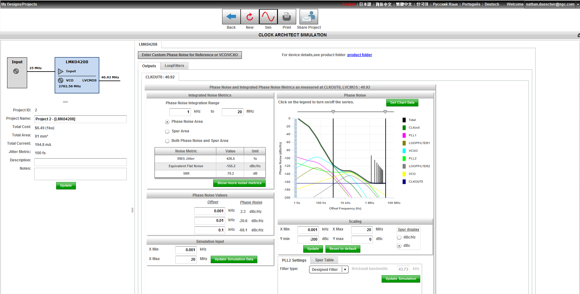
Part Number: LMK04208


Hello,

I'm looking for a jitter cleaning solution that can remove large amounts of jitter (up to 5ns of jitter). Does such a solution exist while maintaining the average input clock frequency?

How much input jitter can the LMK04208 handle?

Thanks,
Nathan

  • Hello,

    I think the LMK04208 could handle the 5 ns of jitter. However what is more important in this case than jitter number is phase noise profile (with spurs). For example if the noise was in a spur at close to the same amplitude of carrier, then it could cause issue for the PLL to lock to.
    - Can you send a phase noise plot (with spurs) of your reference such that I may provide a better answer? Otherwise I might suggest using an LMK04208 evm to check with your 5 ns jitter reference.
    - What's your source/reason for the added jitter? Is it some recovered clock needing cleaning?

    The other consideration, is if the jitter causes instantaneous phase jumps of > 40 ns, the PLL1 digital lock detect may be fooled into thinking it is not locked, although the PLL is still averaging the clock input frequency.

    73,
    Timothy
  • I'm using DDS (direct digital synthesis) for clock frequency generation. Typically a DAC along with a reconstruction filter is used to synthesize these DDS generated frequencies.

    I'm looking into the possibility generating a clean clock by simply taking the sign-bit of the DDS output (which averages to the correct frequency) but it has extremely large jitter typically as large as the period of the clock driving the DDS. I was curious if there are any PLL clock jitter cleaners that can smooth out the jitters and duty cycle.

    Examples of various DDS sign-bit frequencies driven by 200 MHz clock

    Spectrum plot for 10.949 MHz DDS sign-bit

    Phase noise plot for 10.949 MHz DDS sign-bit

    These images were captured while clocking the DDS using a low performance oscillator. I will soon be implementing a high-performance oscillator which should help.

    Think there might be a PLL solution that can handle these?

  • Given that your harmonics are > 10 dB less than fundamental, I don't expect any issues using LMK04208 or other devices. Note that we do have some minimum slew rate specs you will want meet for low frequencies like 10.9 MHz.

    73,
    Timothy
  • Thank you for your help. Are you able to provide further insight as to how the output of the PLL will look with this input? Will the harmonic spurs near the baseband be amplified or reduced?

  • In the webench tool, you are able to load the noise profile of the input and the VCXO then simulate to see the results.

    If changing the VCXO frequency, this must be done in 'advanced mode' for PLL1 (VCO) and then also for PLL2 (PDF). Typically these two numbers will be the same unless the PLL2 R divider reduces the VCXO frequency locked by PLL1.

    73,
    Timothy
  • I entered a custom noise profile in the webench tool which is shown by CLKinX in the graph. The CLKOUT0 of the graph remains as a flat line at -164 dBc/Hz at all frequency offset values. Is this an accurate representation of the output signal?

    In the table "Phase Noise Values" I have entered 1 Hz (2.3 dBc/Hz) 10 Hz (-20.6 dBc/Hz) and 100 Hz (-68.1 dBc/Hz). Do these phase noise values represent the input (CLKinX) or the output (CLKOUT0)?

  • What this shows, is that below 1 kHz, the CLKin input noise is dominating.  However above 1 kHz the noise is attenuated by the PLL1 loop filter and the VCXO noise dominates [hence the importance of having the proper phase noise of the VCXO entered], then PLL2/VCO noise, and finally clkout0.  What CLKOUT0 is is the output buffer contribution.  This can change for carrier frequency, but vs offset frequency, it's the same.  The total noise is the black line which is the actual noise at the CLKout0 output considering all noise sources.

    PLL1 auto designs to 75 Hz BW, 70 degrees phase margin, this is to provide a narrow filtering function.  You may consider trying say 40 Hz loop bandwidth and 50 or 55 degree phase margin.  The 40 Hz is will result in the PLL1 filtering input noise starting at a lower offset frequency.  Using a phase margin of 50 to 55 degrees will result in more peaking at the loop bandwidth, but a sharper cut for the filter.  Since PLL1 typically has a narrow loop bandwidth less than the jitter integration area of concern, this is no problem with a slight increase in the peakiness of the filter.

    73,
    Timothy

  • Okay, so the total noise (black line) will always reflect the signal with the largest noise at that frequency offset. Thus is it correct for me to say that the LMK is not capable of reducing the phase noise of an input clock?
  • The LMK can reduce the phase noise of the input clock. The input noise is actually "pushed down" by the PLL loop pass filter. If you change the loop filters to be wide, you will see the unfiltered clock noise profile (you will also see PLL noise contributing at higher offsets).

    You may find the Choosing Loop Bandwidth for PLLs to be of use, on the E2E clocking page, or here is the direct link: http://e2e.ti.com/support/clocks/m/videos__files/664163.aspx

    73,
    Timothy

  • That PDF document was extremely helpful, it cleared up a lot of my confusions regarding PLLs and phase noise, thank you.


    I'm trying to figure out whether the LMK04208 (or any other Dual PLL device) is capable of synthesizing the following output frequencies

    - 10.00 MHz

    - 10.949296875 MHz

    - 40.92 MHz

    The TI WEBENCH tool claims the LMK04208 is capable of doing a combination of any two of these frequencies but not all three.

    The Clock Design Tool isn't able to generate a single solution of doing more than one of these output frequencies for any device, ref freq, ocxo freq.

    Which tool should I trust? How can I verify?

    Thanks,