This thread has been locked.

If you have a related question, please click the "Ask a related question" button in the top right corner. The newly created question will be automatically linked to this question.

LMX2582: How should I use it with MCU?

Part Number: LMX2582

Input signal : 26MHz

I want output : 920MHz, but I failed.

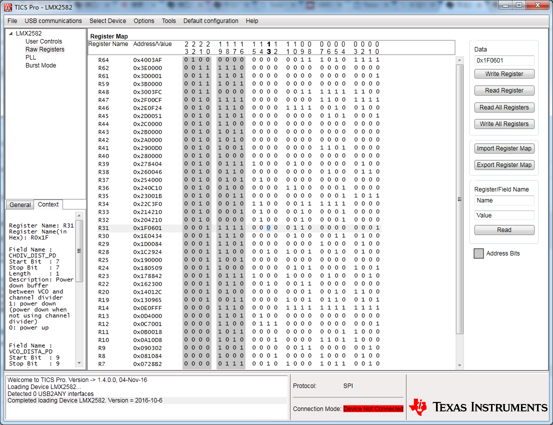
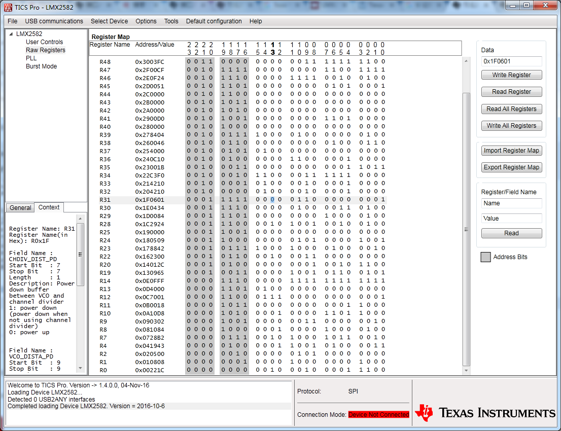
According to TICS pro, I get :

Register map:

I use MCU to set registers of LMX2582.

I connect 3 port of MCU to LMX2582: CSB , SCK  and SDI.

I write registers of LMX2582 according to register map.

This is code of MCU to write registers:

int main(void)

{

  uint32_t reg[44] = 

                                                                                                       {0x00221A,0x010808,0x020500,0x041943,0x0728B2,0x081084,0x090302,0x0A10D8,

                                                                                                        0x0B0018,0x0C7001,0x0D4000,0x0E0FFF,0x130965,0x14012C,0x162300,0x178842,

                                                                                                        0x180509,0x190000,0x1C2924,0x1D0084,0x1E0434,0x1F0601,0x204210,0x214210,

                                                                                                        0x22C3F0,0x23001B,0x240C10,0x254000,0x260046,0x278404,0x280000,0x2900D0,

                                                                                                        0x2A0000,0x2B0000,0x2C0000,0x2D0051,0x2E0F24,0x2F00CF,0x3003FC,0x3B0000,

                                                                                                        0x3D0001,0x3E0000,0x4003AF,0x00221C};     //   register map

         SystemInit();

         GPIOInit();

         GPIOSetDir(PORT0,9,1); //CSB

         GPIOSetDir(PORT2,2,1);//CLK

         GPIOSetDir(PORT0,6,1);//DATA      

        SPI_Wdata(reg,44);//WRITE REGISTER

}                          


void WR_byte(uint32_t da)

{

             int j;

             for(j=0;j<24;j++)

             {

                        GPIOSetValue(PORT0,6,(da&0x800000));   

               GPIOSetValue(PORT2,2,1);    

                        da = da<<1;

               GPIOSetValue(PORT2,2,0);

             }

}

void SPI_Wdata(uint32_t *Tdata,uint32_t size)             

{

         int i;

          GPIOSetValue(PORT2,2,0);

           GPIOSetValue(PORT0,9,1);

         for(i = 0;i < size;i++)

         {

  GPIOSetValue(PORT0,9,0);

  WR_byte(Tdata[i]);     

  GPIOSetValue(PORT0,9,1);

         }

}

Am I wrong?

How should I set register of LMX2582?

  • Hello,

    Did you export the register map from the TICS Pro software? You can then use this in your software. I didn't see some of the earlier register programmings like R64, R62, R61, etc... exporting the register map can simplify/reduce copy error chance.

    You should program all registers in the same order as listed in TICS Pro.

    --

    I didn't look closely at the actual code to bit-bang the data out. Did you check the output on a scope as compares to the datasheet? Have you considered using the SPI module to send the data out?

    73,
    Timothy
  • I was just noticing, your VCO frequency box is red, I think this means it is out of range. You need to adjust the PLL N value to get the VCO into the proper range.

    73,
    Timothy
  • Tim, you're right, the VCO box has to be within 3550 to 7100MHz.

    Tao, please double the N value to get VCO in the right range, then double channel divider to get the same 920MHz.

  • Timothy,

    Hello !
    Thanks for your answer!
    I dont have LMX2582 EVM.
    I have exported the register map from the TICS Pro software. I am sure than all the registers are programmed.
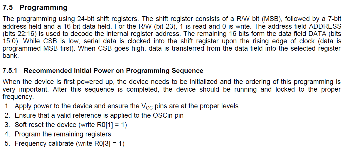
    And I program all registers in the same order as listed in TICS Pro. According to the datasheet:
    "7.5 Programming
    The programming using 24-bit shift registers. The shift register consists of a R/W bit (MSB), followed by a 7-bit
    address field and a 16-bit data field. For the R/W (bit 23), 1 is read and 0 is write. The address field ADDRESS
    (bits 22:16) is used to decode the internal register address. The remaining 16 bits form the data field DATA (bits
    15:0). While CSB is low, serial data is clocked into the shift register upon the rising edge of clock (data is
    programmed MSB first). When CSB goes high, data is transferred from the data field into the selected register
    bank.
    7.5.1 Recommended Initial Power on Programming Sequence
    When the device is first powered up, the device needs to be initialized and the ordering of this programming is
    very important. After this sequence is completed, the device should be running and locked to the proper
    frequency.
    1. Apply power to the device and ensure the VCC pins are at the proper levels
    2. Ensure that a valid reference is applied to the OSCin pin
    3. Soft reset the device (write R0[1] = 1)
    4. Program the remaining registers
    5. Frequency calibrate (write R0[3] = 1) "


    I have changed VCO frequency box to be not red(VCO frequency is 3609MHz). It is not out of range now. The actual code to bit-bang the data out is wrote by using the SPI module.

    I still failed:
    1. PLL is not locked. Output is not right.
    Whatever signal(26MHz, 27MHz,28MHz......) I input, I always get 876MHz signal. And then I close input, but the 876MHz signal still exists. Why ?
    2. I cant readback registers.
    After I write MUXOUT_SEL = 1 and set R/W bit to 1, I programm some registers to the device. But no data is output at the MUXout pin.

    THANKS!
  • Brian,
    Thanks!
    Please see my reply to Tim.
  • Hi! Have you solved your problem?