This thread has been locked.

If you have a related question, please click the "Ask a related question" button in the top right corner. The newly created question will be automatically linked to this question.

LMC555: LMC555

Part Number: LMC555


Dear TI, 

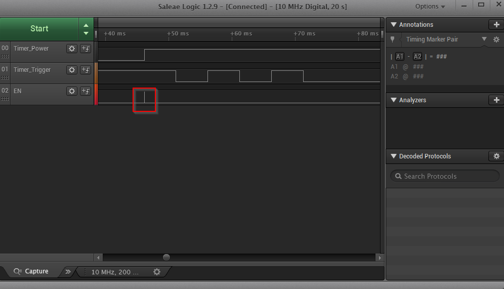
I am using a LMC555 timer to enable a booster, which will then power my motor driver, please the attached schematic. What I do in my software is that I first pull high the "Timer_Power" GPIO so I can power up my timer circuit. Then I toggle the "Timer_Trigger" GPIO, and once the Timer_Trigger GPIO toggles, the EN GPIO should be pulled high in order to power up the booster. However, when I measure the activity with a logic analyzer, (see attached picture) the EN GPIO is pulled high for very short period (0,4 micro-second to be precise) whereas it should stay high for longer period? Also, the EN GPIO goes high fairly early compared to the Timer_Trigger toggling.

Could you please help me explaining why this timer circuit behaves in this way?

Have I done something wrong on the Hardware level?    

In case you need further explanation or clarifications, please do not hesitate to ask. 

Thanks in advance.

Best regards,

Ahad Azimi

  • Ahad,

    On initial powerup C31 is 0V and C30 is charged to "timer_trigger" voltage.
    Therefore a output pulse will occur because trigger will be 0V on power up.
    The output pulse will be short because the control voltage has not risen to 2/3 * VCC yet.
    Remove C30 to get proper one-shot time just after power up.
    I don't know why "timer trigger" does not output anything at time = 52ms , 62ms and 72ms

    In your waveform can you draw the desired signal?
  • Dear Ronald,

    Thank you for your reply.
    This output pulse makes sense, but I was also expecting to see output voltage at 52 ms where it stays high at least until 72 ms. Based on my RC network (R20 and C29), the output voltage-time should be high for at least for 500 ms, once the trigger input receives signal?

    I also removed the C30, but I still see the same pattern?

    Yes, I can draw a desired waveform.

    Best regards,
    Ahad Azimi
  • Ahad,

    LMC555 has a simple input priority list. Reset has priority then Trigger and finally Threshold as lowest priority.
    If RESET is high and TRIGGER is low then OUTPUT output has to be high.
    Have you tried using an oscilloscope? The logic analyzer may be omitting important information.