This thread has been locked.

If you have a related question, please click the "Ask a related question" button in the top right corner. The newly created question will be automatically linked to this question.

LM555: Asking for the LM555 schematic reference design

Part Number: LM555
Other Parts Discussed in Thread: NE555, LMC555, TLC555

Hi Team,
Customer would like to use LM555 to send out PWM duty cuty 15% in 25KHz modulation frequency.
Could you provide the recommended RA and RB and C? is that ok to follow figure 14 circuit?

Thanks,
SHH

  • SHH,

    I'll start with duty cycle formula and solve for Ra
    D = Rb / (Ra + 2Rb)
    (Ra+2Rb) = Rb / D
    Ra = Rb / D - 2Rb
    Ra = Rb * (1/D - 2)
    Ra = Rb * (1/15% - 2)
    Ra = Rb * (1/15% - 2)
    Ra = Rb * 14/3

    Now I'll move to frequency formula and solve for Rb and C
    F = 1.44 / [(Ra + 2Rb) *C]
    (Ra + 2Rb)*C = 1.44 / F
    (14/3*Rb + 2Rb) * C = 1.44 / F
    20/3*Rb*C = 1.44 / F
    Rb = 3/20*1.44/(F*C)

    Based on chart 1nF to 10nF is good.
    I'll pick 1nF
    Rb = 3/20*1.44/(25kHz*1nF)
    Rb = 8.64k; Ra = Rb*14/3 = 40.32k

    However the formulas do not compensate for propagation delay.
    For NE555, I substitute F * (1+F/350kHz) for F. LM555 correction will be similar.
    New F used is 25kHz * (1+25kHz/350kHz) = 26.786 kHz
    Rb = 3/20*1.44/(26.786kHz*1nF)
    Rb = 8.064k; Ra = Rb*14/3 = 37.63k
  • Hi Ronald,

    Thanks for great support.

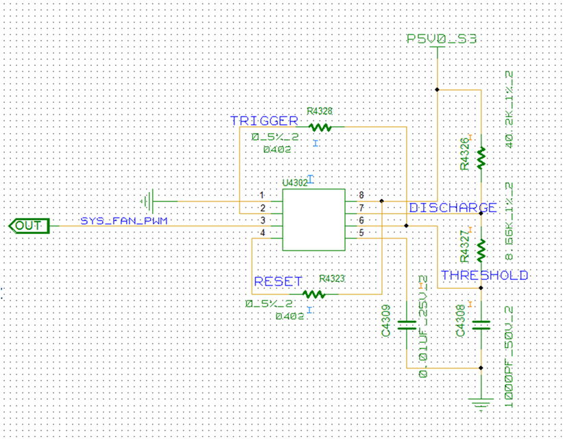
    Could you help review the schematic?

    Thanks,

    SHH

  • Hi Ronald,
    Could you help review the schematic?
    Thanks,
    SHH
  • SHH,

    I suggest a bypass capacitor between pins 8 & 1 (VCC and GND)

    I want to test the timing components. I believe I can find time on Thursday to do this.

  • SHH,

    I built the board with the values close to my  Rb = 8.064k; Ra = 37.63k prediction but the output frequency was too low due to higher propagation delay than expected.

    I picked new resistors scaled by observed frequency error and capacitor tolerance error. Using closest 1% resistor, the new Rb is 7.15k and Ra is 33.25k.

    My test resistors were within 0.2% stated value however the capacitor was 8.1% higher than 1nF.

    Therefore I expect the capacitor tolerance will be the largest variable for frequency but it should not affect duty cycle. The LM555 will add some frequency variability due to propagation delay variance.

    I noticed that the duty cycle is for the low output. The output was low 16% of the time. If a ~15% output high time is needed then the output can be inverted.

    Sample  Freq kHz N DC % Ideal cap
    1 23.203 16.032 25.082
    2 23.138 16.084 25.012
    3 23.211 16.044 25.091
    4 23.185 16.030 25.063
    5 23.204 16.022 25.084
    6 23.188 16.036 25.066

    The samples match well, but they all came from the same bag. 

  • SHH,

    If I use the new values of Rb is 7.15k, Ra is 33.25k and C = 1nF using the data sheet formulas I get the following result.

    Duty cycle is 15.05% ; remember this is a low time duty cycle.
    Frequency is 30.32 kHz ; I had to try for 30kHz to get 25 kHz.
    So LM555 at 25kHz has negative duty cycle that is 1% higher than formula predicts.

    If accuracy is important then TLC555 or LMC555 would be better choices.

  • Hi Ron,
    Appreciate for help.
    So if using LMC555, the schematic is the same. right?

    Thanks,
    SHH
  • SHH,

    The schematic will be the same. Using your initial values of 8.66k and 40.2k should provide 24.7 kHz at 15% low time if C3408 is accurate.
  • Hi Ron,
    If customer need inverted waveform, which device you will suggest to add?


    Thanks,
    SHH
  • SHH,

    a simple inverter using a single NPN or NMOS transistor is common.