This thread has been locked.

If you have a related question, please click the "Ask a related question" button in the top right corner. The newly created question will be automatically linked to this question.

CDCM6208: Meeting Jitter requirement of K2H using crystal

Part Number: CDCM6208
Other Parts Discussed in Thread: 66AK2H12, LMK03328

Hi,

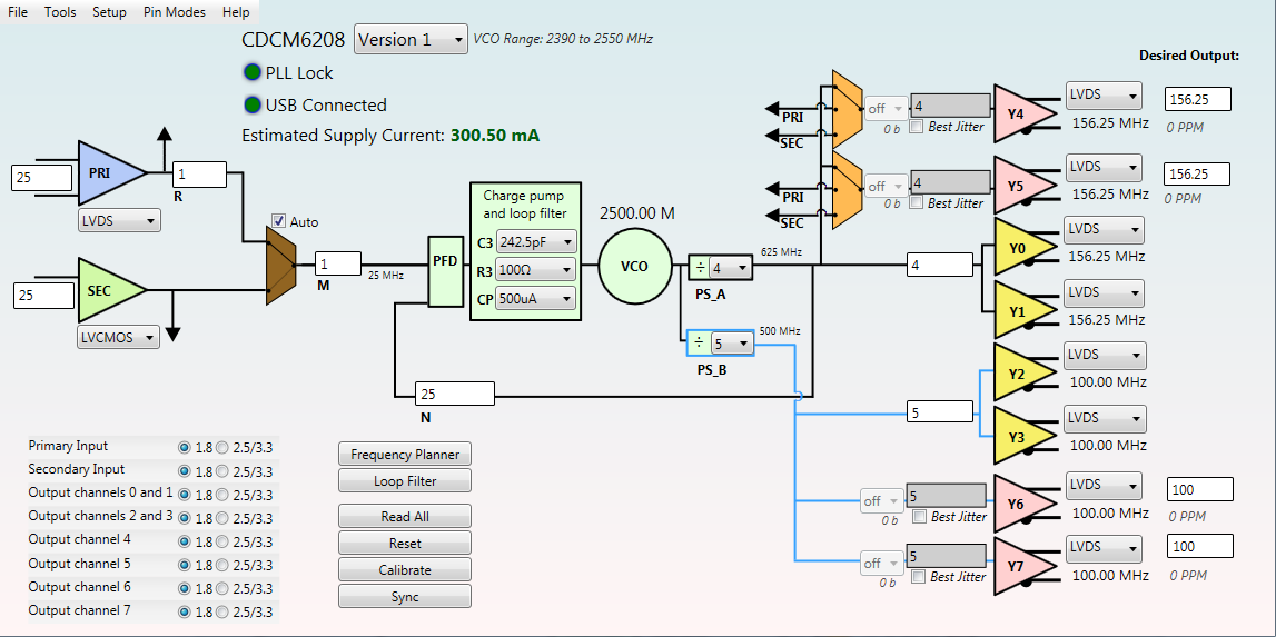
I am planning to use CDCM6208 to clock a K2H soc, using a 25MHz crystal at the SEC_REF pin. 

Using the crystal mentioned in CDCM6208 datasheet ( NX3225GA), Please let me know whether is it possible to attain jitter requirements of K2H device?

Thanks & Regards,

Madhu

  • Hi Madhu,

    With the crystal mentioned in the CDCM6208 datasheet, you should be able to obtain the typical jitter performance: "less than 0.5 ps-rms (10 k - 20 MHz) or 20 ps-pp on output using integer dividers and is between 50 to 220 ps-pp on outputs using fractional dividers depending on the prescaler output frequency." (from datasheet page 26)

    Taking a look at the jitter requirements for the 66AK2H12 as an example, the CDCM6208 should fulfill all the jitter requirements in integer mode. If frequencies that require a fractional output are needed, the performance may not be good enough and in that case, I would recommend the LMK03328 as an alternative- to generate fractional output frequencies, it uses a fractional PLL feedback divider rather than the fractional output divider of the CDCM6208, leading to much improved performance.

    Regards,

    -Tim

  • Hi Tim,

    Thanks for the suggestion.

    The K2H SOC needs 7 clock inputs, so I need to use outputs with fractional dividers. As per CDCM6208 datasheet, fractional divider outputs have jitter between 50 to 220ps p-p depending on pre-scalar output freq. 

    So please let me know how pre-scalar frequency depends on output jitter.

    As per 66AK2H12 datasheet, jitter must be less than 2ps ( rms). I would also like to know how to convert this to p-p jitter.

    Regards,

    Madhu

  • Hi Madhu,

    RMS and peak to peak jitter are slightly different ways of quantifying timing jitter. RMS is a measure of random jitter while peak to peak is a measure of total jitter. To convert between the two, a bit error rate factor needs to be defined. It would be quite lengthy to fully define the conversion between the two here but there are several excellent app notes available on the web which can help explain, including this one: 

    Both the CDCM6208 datasheet and 66AK2H12 datasheet outline requirements for RMS and peak to peak jitter and it looks like using the integer dividers, the CDCM6208 will be suitable. See table 2 on page 27 of the CDCM6208 datasheet for both RMS and peak to peak jitter specs.

    Note that the fractional dividers only show reduced performance if they are actually used to divide the pre-scalar frequency by a fraction to obtain the final output frequency. If you use a fractional divider in 'integer mode' and divide the pre-scalar frequency by an integer, you will still see integer divider jitter performance. Therefore depending on the 7 frequencies you need, you may be able to configure the dividers so that they are all integer dividers. I can assist with this as well if you have a frequency plan in mind.

    If you must divide by a fraction, the value of the fractional divider will affect the output jitter. This will depend on the pre-scalar frequency and the output frequency you need. In general, fractional dividers close to integer values will cause larger spurs on the output, resulting in worse performance. For example, dividing by 2.01 will yield worse jitter performance than dividing by 2.5. The pre-scalar divider can be set to maximize fractional divider performance by giving you some flexibility in which divide value you can use.

    Regards,

    -Tim

  • Hi Tim,

    Thanks for the information.

    I need Four 156.25MHz and Four 100MHz clocks, and I have planned output as indicated in below image.

    The EVM tool mentions that output is 0 PPM.  But could you please explain is there any relation between ppm and output jitter ?

    Regards,

    madhu

  • Hi Madhu,

    I recommend the below frequency plan- it is possible in this case to set all the fractional dividers to integer mode. This way the CDCM6208 should easily meet all the K2H jitter requirements.

    The PPM has no relation to output jitter- it is simply an indicator of how much frequency error there is. For some frequencies, the resolution of the fractional output divider is not great enough to generate the exact output frequency you want, so it gets as close to it as possible and the error is displayed in PPM.

    Regards,

    -Tim

  • Hi Tim,

    Thanks a lot for support.

    Please clarify the below doubts:

    1) I am using only 25Mhz crystal for generating all these. I would like to confirm is there any chance that this would degrade the output clock quality.

    2) When fractional dividers are used in integer mode ( ie., integer division instead of any fraction), the output jitter will be same as the integer divider output. Please correct if i am wrong.

    Regards,
    Madhu
  • Hi Madhu,

    1. It should not degrade the output clock quality- the typical jitter measurements in the datasheet were taken with a 25MHz source.

    2. Yes, this is correct- using a fractional divider in integer mode will yield the same jitter performance as an integer divider.

    Regards,
    -Tim