This thread has been locked.

If you have a related question, please click the "Ask a related question" button in the top right corner. The newly created question will be automatically linked to this question.

CDCE949: Which is better between the following two PLL settings in CDCE949?

Part Number: CDCE949

Hello,

I would like to create 25 MHz PLL out and I have found two PLL settings:

- Input clock is 27 MHz.

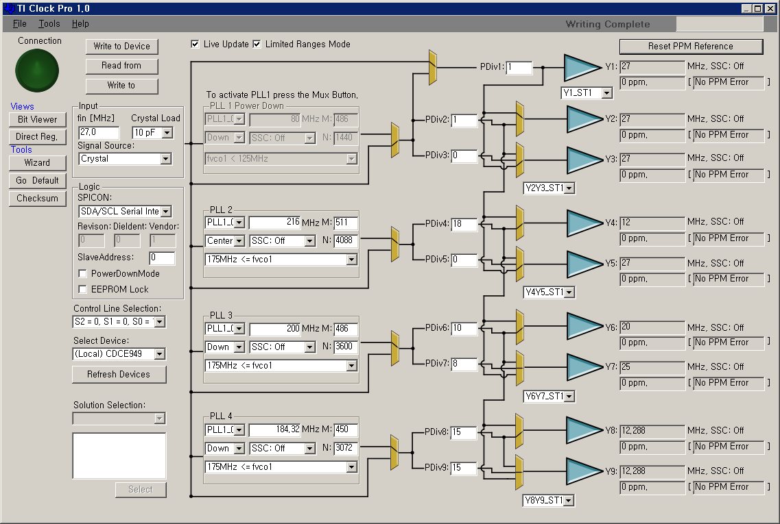
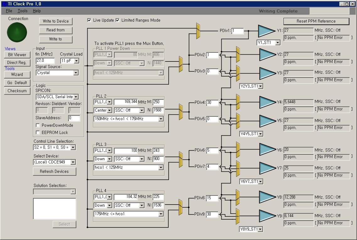
- Y7 is my target PLL in the attache TI Clock Pro capture file.

1.  first settings (2015_1223)

           M = 486

           N = 3600

           Pdiv = 8

2. second settings (2017_0217)

           M = 243

           N = 900

           Pdiv = 4

The final output clocks are all 25 MHz.

   - Fout = Fin/Pdiv x N/M (CDCE949 datasheet p.25) 

My question: 

Which is better settings between the two ones?

The first one is what TI clock pro shows to me.

The second one is what I have changed from the first one in such way to make the M, N and Pdiv smaller.

The attached files are  TI Clock pro capture files for the two settings.

Thanks.

  • Hi Jay,

    The first configuration with the higher PLL frequency will yield better phase noise performance. A quick test with the EVM on a phase noise analyzer shows this to be the case. With an integration bandwidth of 10kHz-5MHz, the first configuration shows an RMS jitter of 17ps, while the second configuration shows a jitter of 37ps.

    Regards,
    -Tim
  • Tim,

    thank you so much.

    So this means that the result from Ti Clock Pro Software is best and we better not to modify PLL settings manually.

    Thanks again.