This thread has been locked.

If you have a related question, please click the "Ask a related question" button in the top right corner. The newly created question will be automatically linked to this question.

LMX2571: LMX2571 Lock time?

Part Number: LMX2571

DEARS.

The customer is currently reviewing the LMX2571 and is using the TI PLL simulation tool.

Ext VCO used by customers ranges from 330 MHz to 440 MHz, Kvco 20 MHz / V.

LMX 2571 setting values are Reference clock 50.4MHz, PDF 4.2MHz, charge pump 0.625mA.

Loop bandwidth 1kHz setting.

When applied at 1kHz in the tool, it is displayed as actual 1.23kHz.

The operating frequency range is 350 MHz to 420 MHz.
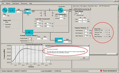
When LMX2571 Ext VCO is applied Lock time 2.72 ms result.

Is fast lock and switching circuitry applied?

If it is the result of an unapplied state, how can the lock time improve?

When applying fast lock / switching circuitry, guidance on lock time (condition within settling frequency 100 Hz) is necessary.

Thank you.

  • Hi Henry,
    The lock time simulation is based on theoretical calculation, fast lock is not included. In fact, I expect the actual lock time should be much longer than 2.7ms because of cycle slipping issue (loop bandwidth much smaller than fpd).
    If your desired loop bandwidth is around 2kHz, I don't think we can make the lock time shorter than 2ms no matter if there is a fact lock or not.
    However, if you are switching between 2 fixed frequencies, you can consider to put it in duplex mode. In this case, the lock time could be made < 2ms. See datasheet section 8.1.5 for details.
  • Dear.

    I need to make sure my idea is right.

    Is the duplex mode of the reply content in section 8.2.2 (PLL duplex mode) of the TI LMX2571 Datasheet?

    In the structure of section 8.2.3 in duplex mode, the frequency of F1 uses an external VCO (with loop bandwidth of 1 kHz), and the structure using internal frequency (loop bandwidth of 100 kHz) has a fixed F2 frequency at time <2 ms Can it be considered impossible to display?

    Also, do you think that a switching circuit for fast lock in section 8.1.5 is not necessary in the structure that uses F1 (using external VCO) and F2 (using internal VCO)?

    thank you

  • Hi Henry,

    The fastlock theory is described in 8.1.5 while an example is illustrated in 8.2.2.
    In 8.2.3, we called this hybrid mode. F1 uses external VCO while F2 uses internal VCO. Switching from internal VCO to external VCO is slower because of the LBW is smaller with external VCO. However, switching from external to internal VCO is very fast, it was 56µs as shown in Figure 81.
    The switch in 8.1.5 is used if both F1 and F2 use external VCO.