This thread has been locked.

If you have a related question, please click the "Ask a related question" button in the top right corner. The newly created question will be automatically linked to this question.

LMX2581: Improvement of SNR

Part Number: LMX2581

Hi,


we try to improve the SNR of a LMX2581 using the differential outputs. The used carrier frequencies for this project are about 70 MHz and 323 MHz with a digital PWR setting from 5 to 30.

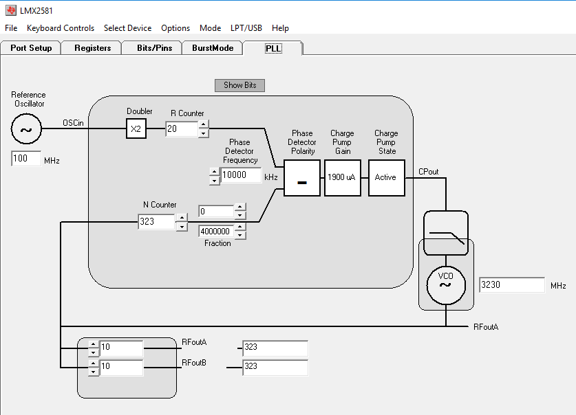
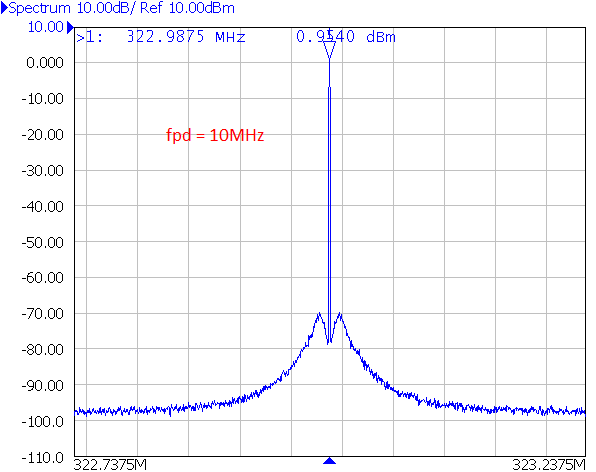
In the attachment you will find a picture of the measured SNR. I applied 30nH inductors -> Z about 50ohms (2*pi*f*L) with OUTx_PWR = 30 and Freq.=322.9875MHZ at this setting. Result: SNR=68.16 dB.

In a previous test I already applied a Balun after the pull-ups but this hadn´t any relevant effect on the SNR. With inductive matching the result was even a bit worse than without Balun.


I plan to raise the given value of the 51R pull up resistors to 100 ohms. I assume that the result is a forced impedance of 100 ohms. To match the impedance back to 50 ohm I want to use the balun with an according impedance ratio. For this example, with 100 ohms, it would be 2:1.


My questions regarding to that:

  1. Which impedance value would you recommend for such an application or which value is suitable for the LMX2581 at all?
  2. According to the LMX2581 datasheet page 21, the relative noise floor is better with inductors. Should I use inductors instead of resistors? If yes, have you an idea where my mistake is using the balun? Maybe its design type? Datasheet: https://ww2.minicircuits.com/pdfs/TC1-1-13MG2+.pdf
  3. Which method would you recommend to improve the SNR of the Synthesizer? Do you have any experience with operational amplifiers (i.e. instrumentation amplifier)?
  4. Can you tell me the S-parameters for the differential outputs? So I can calculate the matching impedance.


Thanks in advance

Adrian

  • Hello Adrian,

    thank you for the detailed summary of the test with LMX2581.

    Here are a few observations:

    1) The SNR you are referring to is perhaps more a spurious free range or some spectral purity. TYpically the SNR would imply some integration over a certain amount of BW. Your application should dictate that.
    2) Getting the most output power may help but spurious response may scale 1:1. I would use the guidance of the datasheet for pull up components. 50 ohm is a good place to start. You may look elsewhere for spectral purity.
    3) I noticed that the "grass" you have on your spectrum analyzer is spaced by about 15 kHz which is about a sync frequency on a CRT diaplay. Could this be the root cause of these spur?
    4) How are you generating 322.9875MHz from LMX2581? are you in frac mode? if you are you will need to study the possible fractional spur you may generate and how to minimize them. Operating in integer mode would be interesting if you do not have frequency step required.

    I hope this helps,

    Regards, Simon.
  • Hello Simon,

    Thank you for your reply.

    1. You are right with this definition. I want to improve SNR and spurs. Marker2 points only on the greatest spur and displays not the SNR.
    2. Yes it may help. It was just a simple idea to improve my signal with low effort. Unfortunately, the datasheet tells not much about phase noise and spurs regarding different impedances or the use of inductors.
    3. I never thought about this before. But I repeated the measurement with a wider span and another spectrum analyzer. The result was the same.
    4. Yes I am in frac_mode. I will check the influence of the integer mode on my signal.

    I will report my results again after I checked the spur sources in the datasheet.

    Regards

    Adrian
  • Hello,

    I am a bit confused about the signal when PLL_Num = 0.

    Why is the Noise, close to the carrier frequency, so high? Can someone explain that phenomenon to me? Please tell me how to use the integer mode correctly. I thought when I enable integer mode and set the fractional numerator to zero I get better phase noise and spurs?!

    In the attachment you will find a screenshot of the Code Loader settings and the signal with PLL_Num = 0.


    Thanks in advance,

     Adrian

  • Hi Adrian,

    Could you try make R-counter to 1 and charge pump gain to 220µA?
    You may also try put CPG_BLEED to 0.
  • Hello Noel,

    Thanks for your advice. I attached the results of your settings plus I experimented with some other settings, higher VCO frequency, modulator order etc. The current setting seems to be the best. Unfortunately, there are still spurs in the signal as you can see…

    Tell me if I am wrong, but I can´t use the integer mode when PLL_Num isn’t zero?! It seems that the signal is the best when the R-counter is 1 as you mentioned. The problem is, that this restriction does not allow to use integer mode.
    Ok, integer mode isn’t compatible for every frequency because PLL_Num has to be zero. But with this further restriction, integer mode would be useless when the remaining parameters will fit for only a few frequencies?!


    Regards,

    Adrian

  • Hi Adrian,

    I am a bit confused, are you looking for 323MHz or 322.9875MHz?

    323MHz is an integer channel, NUM is equal to 0, the setting of fractional order is not matter, you should get clean signal even if you use 3rd order.

    322.9875MHz is a fractional channel, there will be some fractional spurs. If you change the configuration a little bit, you can push these spurs away from the carrier and as a result the spurs levels are reduced.

    With OSCin freq = 100MHz, I don't think we need doubler anymore. Change the fractional denominator to the max. value. Use div/8 to change the VCO frequency. This way, the spurs frequency will be pushed away from the carrier. Change PFD_DLY to make the phase noise looks better.

    Here is the test result with fpd = 10MHz and 50MHz.

  • Sorry, the first plot should be this one.

  • Hi Noel,

    thank you for your detailed answer. The test result with fpd=50MHz looks pretty good. I will try these parameters in my application.

    Sorry, I forgot to mention that i use 323 and 322.9875 MHz. I also use other frequencies. The range is between 200 and 400 MHz.
    For feasibility analysis I tried to get the best setting for single frequencies. I chose 323 MHz because integer and fractional mode was possible. 322.9875 MHz is a typical used channel in our applications. As you already mentioned this is a fractional channel. Because every channel must have similar SNR and Spurs i have to use the fractional mode for every frequency but I had to check if integer is much better than fractional mode (of course only for suitable frequencies).

    i will post my results after my next measurement

    Regards,

    Adrian