Hello all,
I have been trying for some weeks now to get the CDCE62005 to work. The problem seems to be the following:
I can pass the primary and secondary input directly to the output with no problems (aux input is not connected).
When I try to pass the Smart Mux to the output, one of three things will happen:
- No output at all
- Constant DC voltage at output
- Extremely jittery square wave at output (When I set the output divider to /10, there will be a stable square wave with a frequency of ~250MHz instead)
This will change when resetting the device, but otherwise it is a stable condition.
I have attached one example configuration file, but I have tried different settings for the Smart Mux and all show the same behaviour.
REGISTERS
0	EB160320
1	EB160321
2	21400102
3	68400303
4	68400314
5	38604EC5
6	84C52B66
7	FD887657
8	80001808

PORTS
0	DD
1	FF
2	DF
3	F9

INPUTS
PRI	10
SEC	10
AUX	0

EXTERNAL COMPONENTS
C4	1
R4	1
C5	1
Consequently, there is no PLL lock and the VCO does not output something useful.
I have tried this with several boards and all show the same behaviour.
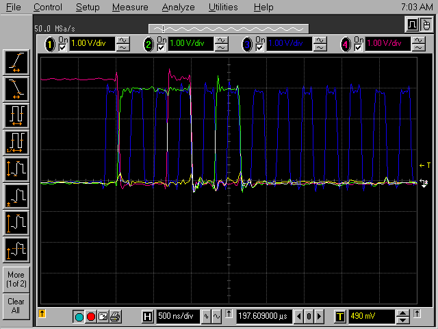
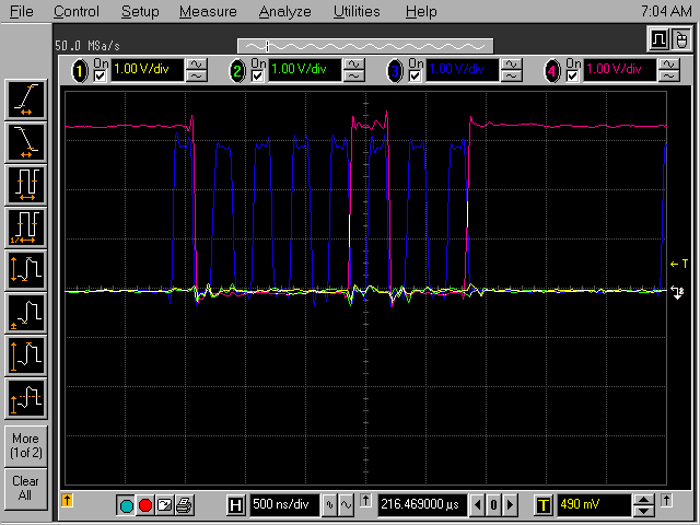
Another thing I have noticed: When I send a read command for register N, the reply is always for register N/2, so I have to shift the register number to the left by one bit. I.e. to get register #1, the command I have to send is 0x0000002E, instead of 0x0000001E, which is stated in the datasheet.
Here are the first bits of the read command (blue is CLK, green is MOSI and red is MISO):
And this are the first bits from the response:
Please don't hesitate to contact me, if you have any questions.
Best regards and thanks for your help,
Daniel


