Other Parts Discussed in Thread: TEST2
Hi, Team:
I am helping customer to simulate the SI of SDCLKout waveform with LVDS output format for a signal output at 122.88MHz.
I have done two tests:
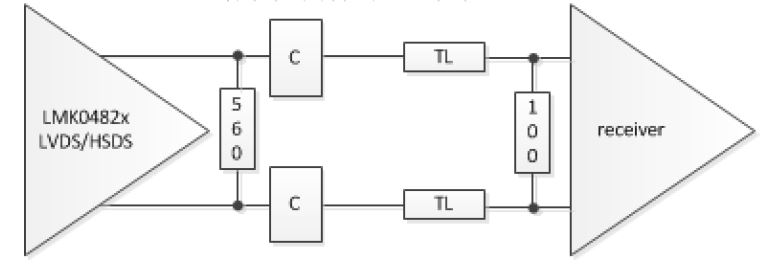
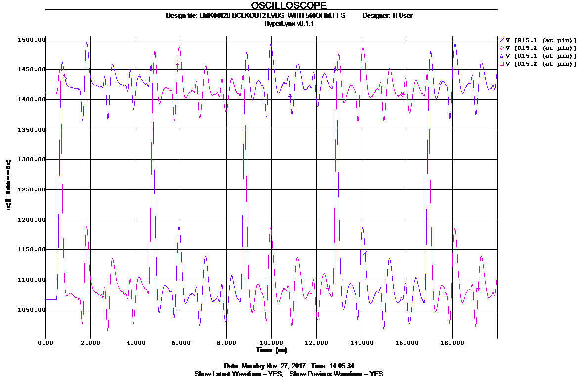
1. First one, I connect 100nF ac coupling cap between LMK04828 SDCLKout output and differential100 Ohm termination. I found the waveform at the two ends of 100 Ohm load resistor is wired as below:
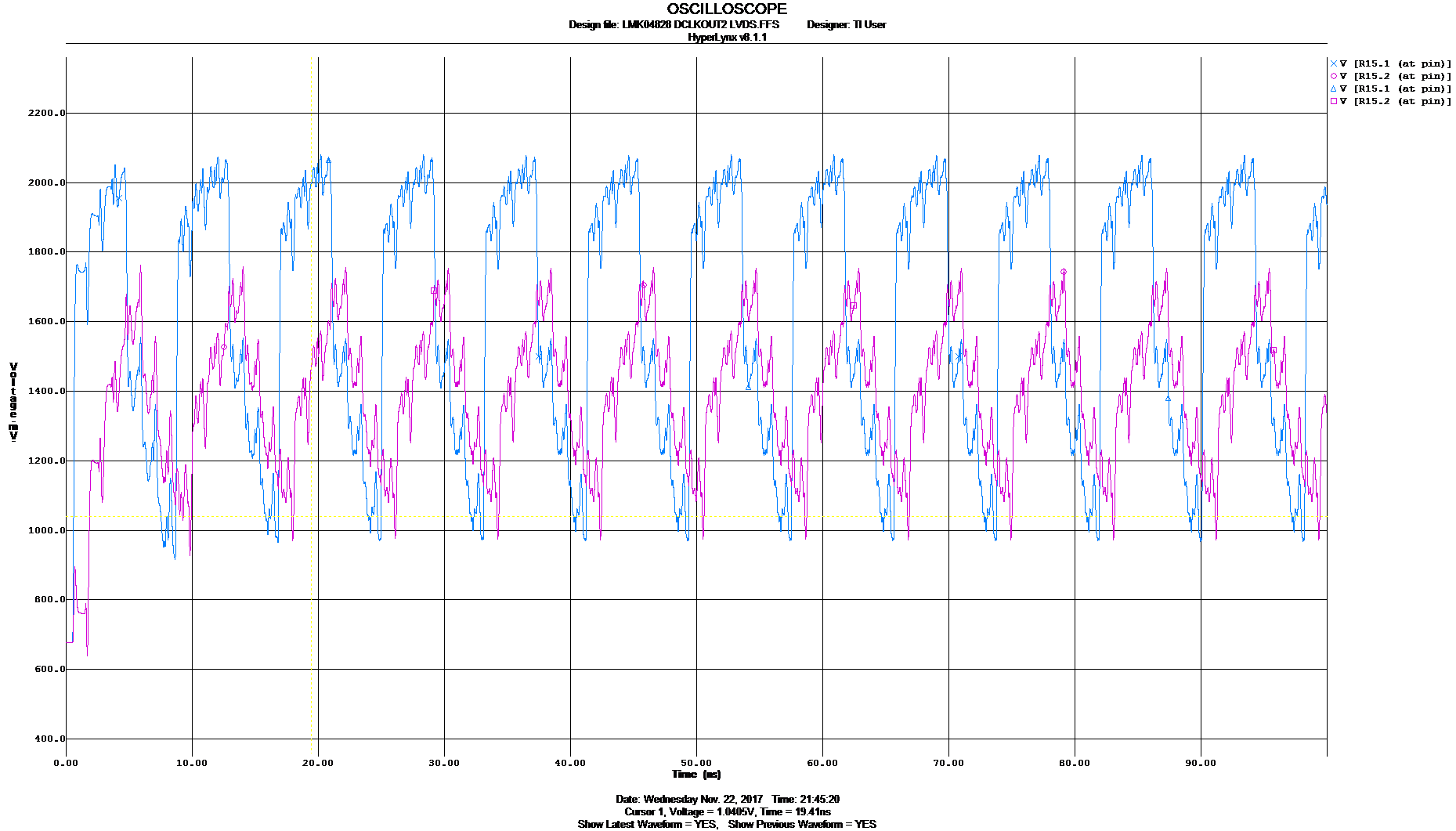
2. The second, I remove the AC coupling caps and do the simualtion again. I found the waveform is more reasonable which has common mode of 1.2V, while it shows a lot of ringing. Do you think this is correct?


May I know why I need to remove the AC coupling cap between the transimitter and load? Could you please help me to check whether the simulation in my second test is correct? I don't know why there is a lot of ringing.
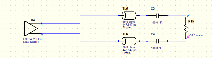
My Hyperlynx simulation file is below: