This thread has been locked.

If you have a related question, please click the "Ask a related question" button in the top right corner. The newly created question will be automatically linked to this question.

LMX2592EVM: Changing Frequency works with TICS Pro but not with MCU over SPI

Part Number: LMX2592EVM
Other Parts Discussed in Thread: TMS320F28027, , LMX2592, USB2ANY

Hi,

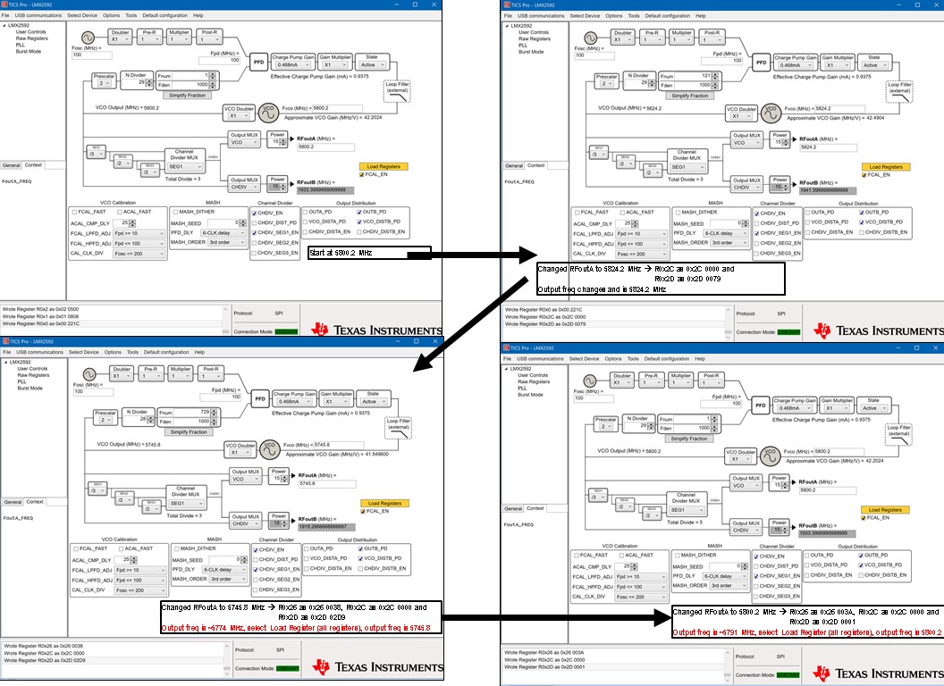
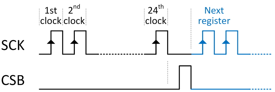
I am trying to change frequencies on the LMX2592EVM using the TI TMS320F28027 LaunchPad via SPI.  The LMX2592 is using the 100 MHz internal oscillator.  I can get the MCU to send all of the register values to the LMX2592 and start transmitting at 5800 MHz.  When I try to change frequencies using the procedure shown in the User's Guide section 7.5.2 (SNAS646E, Jul2017 version), the PLL doesn't change to the target frequency.  Instead it changes to +48 MHz from the original frequency.  If I change the starting frequency, it continues to change to approximately +48 MHz instead of the 2nd target frequency.  Is there a bit field that needs to be enabled/disabled to cause the PLL to accept the new frequency?  I am following the register value changes that TICS Pro performs when changing frequencies using the USB2ANY directly connected to the LMX2592EVM.

Rob

  • Hi Rob,

    If your frequency change involves the change of N-divider, PLL numerator and denominator only, the procedure described in the datasheet is correct.
    What frequency do you want to change from 5800MHz? Could you provide a screen shot of TICS Pro?
    Are you having problem programming the device with the MCU but not with USB2ANY?
  • Hi Noel,

    Correct; I am able to successfully change frequencies with USB2ANY/TICS Pro but not with the MCU.  I have attached a screenshot collage of all TICS Pro frequency changes.

    For the first change, I am trying to change from 5800.2 MHz to 5824.2 MHz and then to 5745.8 MHz, so the only register values that change are R38 (when changing between 57xx and 58xx) and R45.  The range of frequencies I am using is between 5725 MHz and 5850 MHz (implementing frequency hopping), so I will need to change both R45 and R38 if going from 58xx MHz to 57xx MHz.  The PLL denominator (R40 and R41) never changes for my hopset.  Even though R44 never changes (always 0 for the range of frequencies in my hopset), I am still writing 0s to the register since that is a step that TICS Pro performs.  I also have the MCU writing the registers in the same order as TICS Pro (Step 2 just says R45 and R44; TICS Pro specifically changes R44 first then R45).

    While troubleshooting with the USB2ANY, I noticed another issue while changing frequencies with TICS Pro.  Changes from 58xx to 58xx MHz only require a change to the RFoutA field and the output frequency is correct.  Any changes from 58xx to 57xx or 57xx to 58xx will not output the correct frequency until I load all registers (see red text in attached screenshots).

    Any help you can provide is greatly appreciated.

    Rob

  • Hi Rob,
    It looks to me that you have forgotten to press the magic key - write R0 (with the FCAL_EN bit = 1) after changing the N-divider and PLL numerator. The magic key is used to initiate VCO calibration.
    From 5800.2 to 5824.2MHz, the frequency change is small and the same VCO core is being used for the new frequency. So there is not much difference whether you do VCO calibration or not and that is why you got it locked.
    However, the change from 5824.2 to 5745.8MHz is big enough that if a VCO calibration is not executed, you may not be able to get it locked to the correct frequency.
    We recommend initiate VCO calibration every time we change the frequency, no matter the change is big or small.
  • Noel,

    I unchecked FCAL_EN and then rechecked it after switching from 5824.2 MHz to 5745.8 MHz, and then the LMX2592 transmits the correct frequency (same result as "Load Registers"). For FCAL_EN, TICS Pro writes R0 as 0x2214 then R0 as 0x221C. When I try to replicate this using the TMS320F28027, I get the same result as I have been receiving. The LMX2592 starts transmitting the initial frequency of 5800.2 MHz then when the F28027 sends the new register values to transmit 5824.2 MHz including R0 0x2214 then R0 0x221C, the LMX2592 transmits 5849 MHz and never changes even though the F28027 continues to send updated register values (5800.2 --> 5824.2 --> 5745.8 --> 5800.2 --> ....).

    Is there something else besides FCAL_EN that I could be overlooking?

    The change sequence code is below. Note, the F28027 has 16-bit registers and the LMX2592 has 24-bit registers hence the pll_register (8 bit register address for LMX2592), pll_data1 (MS 8 bits for LMX2592) and pll_data2 (LS 8 bits for LMX2592). I have an IF statement before this FOR loop that updates the register values (stored in the F28027) based on the next frequency I want the LMX2592 to transmit.

    Rob


    for(change_step=0; change_step<7; change_step++)
    {
    if(change_step==0) // Frequency Change Step 1: set new N divider
    {
    sdata[0] = pll_register[14]; // write R38=0x2600
    sdata[1] = pll_data1[14]; // write R38 value (MS 8 bits)
    sdata[2] = pll_data2[14]; // write R38 value (LS 8 bits)
    }
    if(change_step==1) // Frequency Change Step 2: set new PLL denominator
    {
    sdata[0] = pll_register[12]; // write R40=2800
    sdata[1] = pll_data1[12]; // write R40 value (MS 8 bits)
    sdata[2] = pll_data2[12]; // write R40 value (LS 8 bits)
    }
    if(change_step==2) // Frequency Change Step 2: set new PLL denominator
    {
    sdata[0] = pll_register[11]; // write R41=2900
    sdata[1] = pll_data1[11]; // write R41 value (MS 8 bits)
    sdata[2] = pll_data2[11]; // write R41 value (LS 8 bits)
    }
    if(change_step==3) // Frequency Change Step 2: set new PLL numerator
    {
    sdata[0] = pll_register[8]; // write R44=2C00
    sdata[1] = pll_data1[8]; // write R44 value (MS 8 bits)
    sdata[2] = pll_data2[8]; // write R44 value (LS 8 bits)
    }
    if(change_step==4) // Frequency Change Step 2: set new PLL numerator
    {
    sdata[0] = pll_register[7]; // write R45=2D00
    sdata[1] = pll_data1[7]; // write R45 value (MS 8 bits)
    sdata[2] = pll_data2[7]; // write R45 value (LS 8 bits)
    }
    if(change_step==5) // Frequency Change Step 3: frequency calibrate disable
    {
    pll_data2[42] = 0x1400; // 4=0100, C=1100, D=1101, E=1110, F=1111
    sdata[0] = pll_register[42]; // write R0[3]=0
    sdata[1] = pll_data1[42];
    sdata[2] = pll_data2[42];
    }
    if(change_step==6) // Frequency Change Step 3: frequency calibrate enable
    {
    pll_data2[42] = 0x1C00; // 4=0100, C=1100, D=1101, E=1110, F=1111
    sdata[0] = pll_register[42]; // write R0[3]=1
    sdata[1] = pll_data1[42];
    sdata[2] = pll_data2[42];
    change_step=7;
    }
    // Transmit data
    for(i=0;i<3;i++)
    {
    SpiaRegs.SPITXBUF=sdata[i]; // Send data
    }
    }
  • Noel,

    I used the USB2ANY and TICS Pro in the RAW Registers mode to manually change the registers (via the Data field on the top right of the screen) one at a time to change frequencies. I noticed that when changing R0, TICS Pro writes a 0221 to the register after I delete the 'C', and then does this again after I delete the '4' before writing 0x221C to the register to re-enable FCAL_EN. The other registers do not write this interim step to the LMX2592. I tried incorporating this 0x0221 write into the change sequence FOR loop, but I am still getting the same result (frequency changes from 5800.2 MHz to ~5849 and stays at 5849 even after calibration; trying to change to 5824.2 MHz).

    Rob
  • Hi Rob,

    Let's ignore what is doing in TICS Pro, the programming procedure for changing frequency is actually very simple - program the new N divider values and then program R0 to calibrate VCO. For example, assume you are locked to 5824.2MHz, now you want to change to 5745.8MHz:
    1. program R38 to 0x260038. This will change the N-divider value.
    2. program R45 to 0x2D02D9. This will change the numerator value.
    3. program R0 to 0x00221C. There is no change to this register but program this register again will start VCO calibration.
    4. you should be able to lock to 5745.8MHz.
  • Hi Noel,

    I took your recommendation and modified the TMS320F28027 code to just program R38 then R45 then R0 for calibrate.  I have the PLL starting at 5824.2 MHz then changing to 5745.8 MHz and then back to 5824.2, etc.  The PLL changes frequencies and transmits when I insert a breakpoint at the FOR loop and step through the write for each register; however, when I try running the code without the breakpoint, the LMX2592EVM transmits the initial 5824.2 MHz then stops transmitting when the FOR loop change procedure executes (to switch to 5745.8). 

    So far, I have tried introducing a clock cycle in between each register write step without any success.  Any other thoughts or recommendations on why the process is working with the breakpoint but not without it?

    Rob

  • Noel,

    I explored the FOR loop delay after writing each register and found that a for loop with 860 cycles is the lowest I can go while still having the code run and change frequencies without breakpoints.

    I'd appreciate any insight you may have on why this FOR loop delay is required when changing frequencies using an MCU.

    Rob
  • Hi Rob,

    A CSB (latch enable) signal is required between each register write. Make sure your code generates similar waveform as below. Right after R0 is programmed, the VCO will calibrate and then followed by analog loop locking. Both of these actions take time. VCO calibration time is around 100us, depending on the configuration. Analog lock time depends on your loop bandwidth. So you should wait sufficient amount of time for the loop to lock to the new frequency before changing the frequency again.