This thread has been locked.

If you have a related question, please click the "Ask a related question" button in the top right corner. The newly created question will be automatically linked to this question.

LMK04826: LMK04826 - SPI Functionality not working

Part Number: LMK04826
Other Parts Discussed in Thread: AFE58JD18EVM

Greetings,

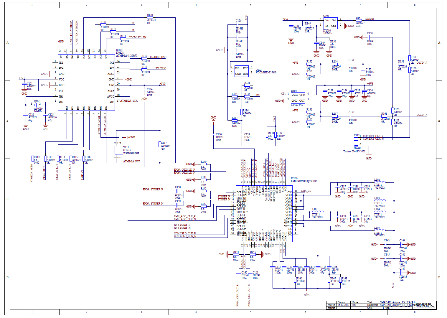
we've recently designed a JESD204b PCB and are attempting to use the LMK04826 as a clock synthesizer / cleaner.  We're having a hard time getting the SPI  to work and we're not sure why it isn't.  We first tried to deactivate 3-wire SPI mode and activate MISO readback on the CLKIN_SEL0 (pin 58) but were never getting any responses when attempting to read a register.  To simplify, we tried to SPI write tests to see if it was even accepting our commands.

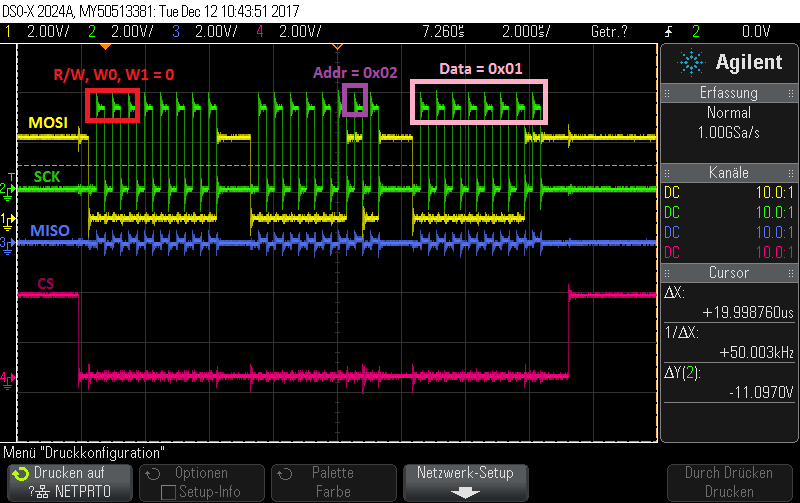
Test 1:  We write to the POWERDOWN bit of register 2, turning it on and off in a cycle and observe the amperage the board is drawing.  Between the two states the current does not change a single milliampere.

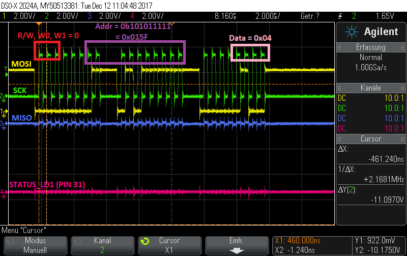
Test 2: We write to register 0x015F (PLL1_LD_MUX), first a value of 3 (Logic low, output - push/pull), then a value of 4 (Logic low, output inverted - push/pull)  We put this in a loop and observed pin 31 (STATUS_LD1) and noticed no change whatsoever. 

Based on these two tests it's obvious that we're not even able to write to the LMK.  Is there something wrong with the SPI protocol we're implementing?  It seems to match the datasheet.  24 bits, clocked in on the rising edge and at 2 MHz.  What could the problem be and what would be the best way to troubleshoot it? 

Thank you very much in advance and we appreciate your help!

Kind regards,

- WBLee

  • Hi Barrett,

    I think you had checked voltage on LMK04926 Vcc pins. If power supply is good, it looks like SPI is locked.

    If there were some wrong SPI operations made anyone of above 3 register value not in default value, then SPI writing to other registers is prevented.

    Could you write these 3 registers w/ default value for LMK04826 before other SPI operations?

    If it is the cause,  we should find when we changed them into unexpected value.

    Did you share SPI MOSI, SCK w/ other slave devices?

    Hope helpful for your debugging.

    Regards,

    Shawn

  • Shawn,

    thank you very much for your reply!  We've checked and double-checked all pins and compared with the datasheet, as well as physically measured each.  The VCC pins are all at 3.3 V and the grounds are properly grounded and at 0.   The LMK has its own SPI bus connected to a microcontroller, and in the firmware we started very basic just trying to get it to react.  We never wrote to the SPI lock registers after power up, but we tried writing to it anyway and nothing changed.  At this point we're running out of troubleshooting steps.  It's possible the IC was damaged some way in the soldering process.

    Thanks again for your assistance,

    - WBLee

  • Shawn,

    we replaced the LMK with a new one and it is exactly the same, so we're assuming that the LMK is probably not defective and that there's something with our design or SPI communication.  I've already posted the SPI communication and you seem to think the protocol looks correct.  I'll post here a screenshot of the schematic to see if anything looks suspicious to you. The design was a virtual 1:1 copy of the AFE58JD18EVM eval-kit.Thank you very much again in advance.

    - WBLee

    Note:  'n.b.' is German for "DNP - do not place" although not every passive that doesn't have an 'n.b.' is on the board.

  • Hi WBLee,
    From Schematics, it looks like RESET pin is pulled high!
    Best regards
    Puneet
  • Puneet....

    Thank you so incredibly much.  That was it.  We'd been working with so many different ICs that were all active low resets that we never even thought about it.  Thank you so very much for this help.  We feel stupid but are also glad it's working now.  Thanks!

    - WBLee