This thread has been locked.

If you have a related question, please click the "Ask a related question" button in the top right corner. The newly created question will be automatically linked to this question.

LMK04828: Clock Output Vpp LOW with LVPECL20 Output format

Part Number: LMK04828
Other Parts Discussed in Thread: LMK04808

Hi:

I use an LMK04828 to provide a sampling clock of DAC, with the ExternalVCO mode(1.728GHz original clock was input to CLKin1, and made DCLKOUT6 to output 1.728GHz clock. Internal PLLs were not used).

The output port is DCLKOUT6, which was set the output format of LVPECL20, and the output P/N pins are pulled-down to GND with 240ohm resistors, as below:

When use differential probe to measure the output amplitude of DCLKOUT6, the result Vpp is about 650mV, as below:

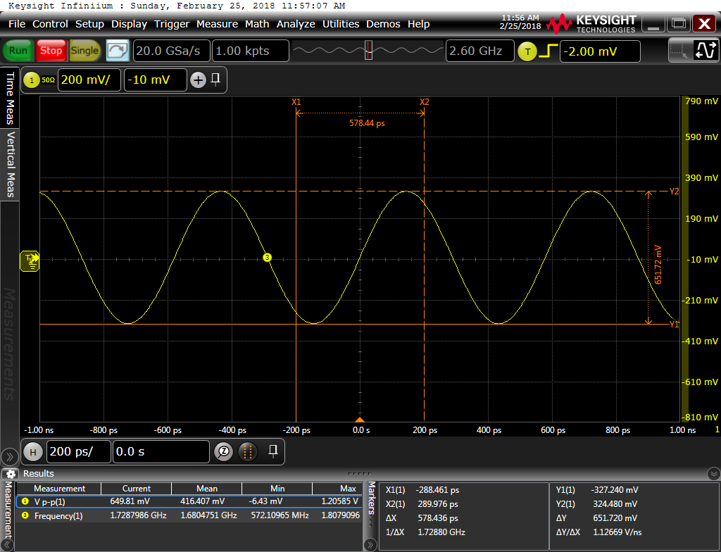
Pay attention that: the Vpp in the screenshot above is differential voltage measured with differential probe, NOT with single-ended probe measuring on one of the two differential signal lines.

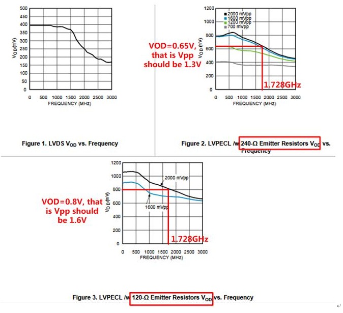
The datasheet says that when output format set to LVPECL20, the VOD is 960mV, so that the differential peak-to-peak voltage is 2*960=1920mV. (Described in datasheet SNAS605AR: Page 27-Figure 9).

So, the measured 650mV is much lower than the desired 1920mV, which cannot meet the requirement of DAC sampling clock amplitude.

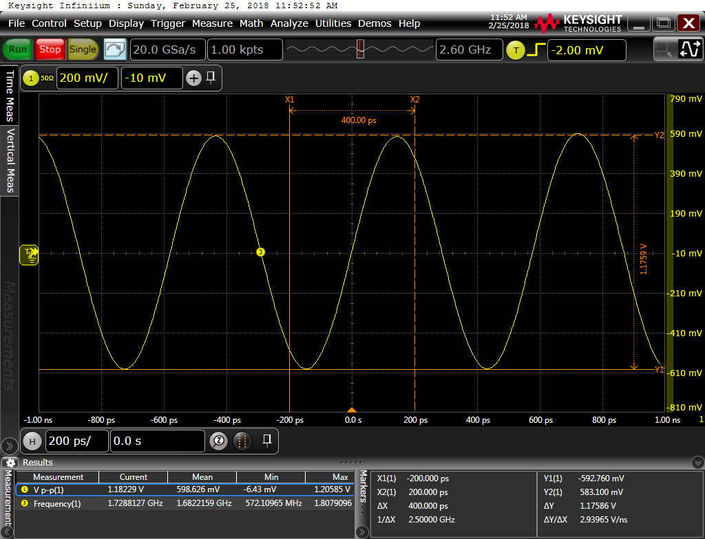
In view of the phenomenon, I changed the pull-down resistors from 240ohm to 50ohm  for both + and - lines, then the output Vpp was increased to 1180mV, which still cannot reach the datasheet-rated 1920mV, as below:

Now, can you find me where the problem may be?

Thank you!

  • Dear user, Someone will look at this issue Monday. thank you for your patience, Regards, Simon.
  • Hi There,

    The output voltage varies with frequency. You may refer to LMK04808 datasheet section 6.7 Figure 2 and Figure 3 for details.
  • Hi:

    I cannot find corresponding instruction about how output voltage varies with frequency in LMK04828 DATASHEET; Only find in LMK04808 DATASHEET.

    Even if the output character of LMK04828 is the same as that of LMK04808, the measured Vpp of 1.728GHz clock output is much lower than the rated value in the figure of datasheet.

    The figure below is found in LMK04808 DATASHEET (NOTE THAT the chip I use is LMK04828, not LMK04808)

    So, can you answer me whether the output character of LMK04828 is the same as that of LMK04808 or not, and how can I make the output Vpp higher?

    Thanks a lot!

  • The actual chip I use is LMK04828, not LMK04808; Moreover, I need to know how to increase the output Vpp to the rated value or near the rated value.
  • LMK04828 has similar LVPECL driver capabilities as LMK04808 , so the measurement result is reasonable. There is no method to continue increasing output swing at 1.728 GHz.
    How about receiver Vpp requirements ?
  • Hi: 

    The DAC requires a sampling clock of at least 1400mV Vpp. Considering the corresponding instructions of Datasheet, LMK04828 should meet that requirement.

    So, are there any possible problems about register configuration or hardware design defect of LMK04828 in my design and application?

    Looking forward to your answer, thanks! 

  • Hi There,

    Couples of idea in my mind:
    What is the bandwidth of your scope?
    What is the capacitance of your probe?
    Can you try 100pF instead of 100nF AC-coupling cap?
    Were you measuring the clock closed to the input of the DAC?
    What is the input impedance and capacitance of the DAC?
  • Noticed waveform was like a sine wave, I agree there are path (on board or test path) bandwidth limitations to make amplitude loss.
    The ideal waveform should be like a square wave, even though it is hard for a 1.728 GHz.
    Let's set our debug target as Noel's Figure 3 (Vod=0.8V, Vpp= 1.6Vpp), which could satisfy DAC's 1400mVpp requirement.