This thread has been locked.

If you have a related question, please click the "Ask a related question" button in the top right corner. The newly created question will be automatically linked to this question.

LMK03328: R12 Register information detail

Guru 19785 points

Part Number: LMK03328

Hi Team,

We have questions about R12 register from customer using LMK03328.

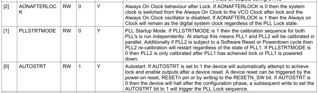
Could you please elaborate the following descriptions for each R12.2, R12.1, R12.0 ?

Q1). R12.2 : What is "always on clock" ? If set to "1" does it mean the output clock is not locked to input clock ?

Q2). R12.1 : What is the difference from the two settings ?
Does it mean VCO Calibration PLL1 and PLL2 run ...

"1" : simultaneously (PLL1 and PLL2 at the same time)
"0" : sequential ( PLL1, then PLL2)

Q3). R12.0 : I am understanding that this bit must be "1" to operate normal for the device. When do you use R12.0 = "0" ?
Best Regards,

Kawai

  • 1. It is the ~10 MHz internal digital system clock. Always set AONAFTERLOCK=1 to keep the internal digital clock alive regardless of PLL lock condition. Do not use setting of 0; it is an internal debug/test bit.

    2. You are correct.

    3. Yes, always set this to 1 if you want the PLL to auto start after reset (hard or soft reset). Set to 0 if you want to prevent PLL auto start (registers are still loaded from EEPROM on hard reset, but PLL lock sequence will not be initiated).

    Alan
  • Hi Alan-san,

    Thanks for the answers.

    Best Regards,
    Kawai
  • Hi Alan-san,

    I have one more question.

    For VCO Calibration, how would the setting differ in characteristic or performance by using PLLSTRTMODE = "0" or "1" ?

    It seems to be better for me to use "1" simultaneous setting rather than the default "0" sequential.
    What would be the advantage and disadvantage for each setting ?

    Best Regards,
    Kawai
  • PLLSTRTMODE=1 is better since it would allow PLL2 to lock independently from PLL1 lock condition, so PLL2 could lock sooner compared to when PLLSTRTMODE=0. I don't see an advantage to using PLLSTRTMODE=0.

    Regards,
    Alan
  • Hi Alan-san,

    Thanks for your comment.

    One question from customer.

    He tested using following conditions.
    - PLLSTRTMODE = "1" : PLLs independent calibration
    - SYNC_MUTE = "1" : Mute all outputs during SYNC
    - Output frequencies are generated using PLL2.
    - PLL1 is not used, however, ENABLED.

    Under this condition, he didn't have any output, however, when he changed SYNC_MUTE = "1" -> "0", he was able to have output.

    From this test result, since PLL1 is stuck under synchronizing condition, device is muting the outputs.

    Do you MUST disable the unused PLL ?

    Best Regards,
    Kawai
  • Yes, they should disable the unused PLL. This will also reduce current consumption. They should also power- down any unused output channels and dividers to reduce current.

    Regards,
    Alan