This thread has been locked.

If you have a related question, please click the "Ask a related question" button in the top right corner. The newly created question will be automatically linked to this question.

LMX2594: Ramping with synchronized ref output

Part Number: LMX2594

Dean,

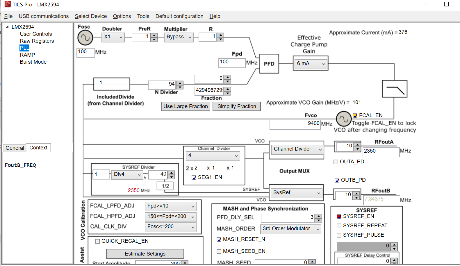
I have a ramp that goes up then down 100 MHz with each leg taking 100us.  This is a nice start.  Now I want to have a signal that is synchronized with the 2594 clock to enable digitizing with an external A/D.  Whenever I try to program the 2594 to do SYSREF_EN mode, it eventually disrupts my ramping.  Here is a screen shot before I go to turn on VCO_PHASE_SYNC 
Here is my setup when I get the synch signal SYSREF to work.  It outputs a nice 14.375 MHz signal.  
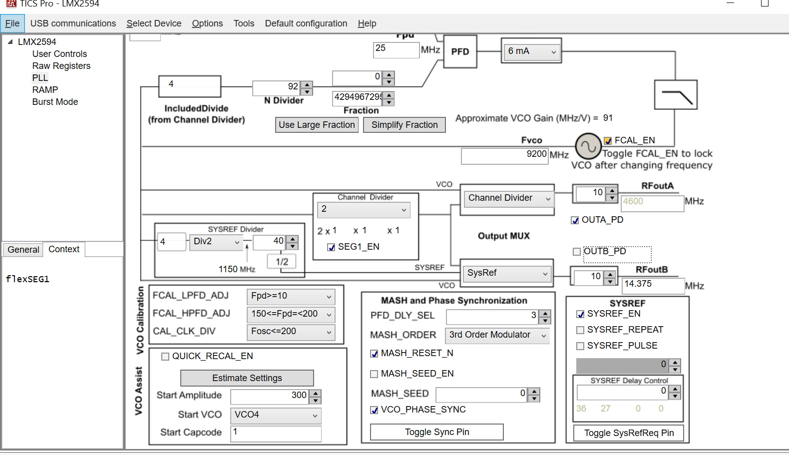
(Don't worry about the channel divider output.  I only have an HP53310A modulation domain analyzer in order to look at the F vs T output, so I sometimes need to channel divide by 4, sometimes just by 2.) 

How can I have a ramp output from the 2594 that I can synchronize against?  Is the SysRef signal not the correct one to use?

Thanks,

Darren R

  • P.s. According to Fig2 in the TIDUD11 document, I believe I am in "Category 1" for synchronization. I want the reference signal to be somewhere in the 10 to 15 MHz range, and my Fout is around 9200.
  • Dear Darren,

    Dean is out of the office for the week. I am happy to help you.

    We have not designed the ramp feature to be used with the sync and sysref mode. I will likely not work together.

    I have a few questions:

    1) Do you need a sysref signal? are you using it for sync or in a 204B link?
    2) Are you trying to sync the ramp or the output signal?

    Can you tell me more about your requirements, it would help me understand better what you are trying to do.

    Regards, Simon.
  • Simon,

    Great to have your help, thanks.

    I need to synchronize with the output so that I can digitize the return through the system.  Ideally I'd like a pulse on the start of each ramp, then I could count them and only sample on every nth one.  I'm going to be sampling in the 10 to 15 MHz sort of range, so I picked having a continuous reference pulse at 14.375 MHz as good enough.  

    Is this the correct avenue to do the synchronization?

    Thanks,

    Darren

  • Simon,

    I'm trying to build an FMCW Radar at XBand.  I envision I will use a bandwidth of less than 100 MHz, but I'm also having trouble getting a nice ramp signal consistently.   I read from you post here that a 'clean' ramp is not always possible, but from my questions to Dean it seems like that refers to cases of very wide sweeping ramps (that may go between the VCOs).  Can I create a clean signal if I keep it to just one VCO?  Similar to that post, I'd also like to synchronize on the ramp to do counting and such.  Was there a way to do that?

    Thanks,

    Darren

  • Darren,

    For calibration free ramping, you have to stay in both the same VCO Core (7 of them) AND VCO capcode (183 of these per VCO core). So if you do 100 MHz, you can likely do it at higher frequencies, but at 9.4 GHz, it is a little marginal that you will get 100 MHz calibration free range, especially at hot temperature.


    As for the SYNC questions ...
    Category 1 ramping has a fraction of zero, but when you enable ramping, this is done by sweeping the fractional numerator, which essentially makes this fraction non-zero and then this is no longer category 1. After ramping is done, it should return back to category 1. Also, this would be talking about the 4600 MHz output, if you are taking about the SYSREF output at 14.375 MHz, this is definintely not synced with the divider. So if you have two separate devices and then you use the SYSREF to sample these ramps, the sampling times of these two devices could be out of phase because the SysRef divider is not SYNCED>
  • Dean,

    I'm still confused some.  

    How can I get as clean a 100 MHz ramp as possible, at 9300 MHz?  Would it help if I were doing the partial calibration assist? If so, is a microprocessor tasked with changing the vco_capctl_start and vco_daiciset_start pins on each ramp?  For this I follow the assist procedure and Table 6?  Would I then be constantly changing the value of register for the capcode and amplitude, at something like 10 kHz?  Is there a timing to this?  How about an example setup or app note?  I'll note, in my present use of the chip I only toggle FCAL_EN one time, namely before I turn on the ramping.  This partial assist discussion makes me think I need to toggle it on every ramp?  Is that correct?

    On my SYNC question, maybe let's backup.  Right now I'm only talking about my single 2594.  I want to perform computations in my DSP across ramps, so that I can ascertain doppler velocity of the targets.  I wish for a signal to denote the conclusion of each ramp.  It seems like the phase SYNC functionality will do this for me: ensuring a deterministic delay between the ramping wave and the input oscillator.  Am I interpretting this correctly?  How can I interface to this feature?  

    Perhaps a phone call will be the best setting for our discussion.  Thanks!

    Darren

  • Darren,

    By "clean", what I am talking about is having the device ramp in a linear way without the VCO having to re-calibrate as shown in figure 10 in the datasheet. IF the VCO has to re-calibrate, then this will be about a 15-30 us interruption while the VCO goes to the next frequecy band. Figure 11 shows an example of this. At 9300 MHz, I locked the device at room temperature and I could change the frequency by 94 MHz upwards and 54 MHz downwards. So you could not do 9300 MHz - 9400 MHz for instance. Maybe you could calibrate at 9350 MHz and then you could ramp 9300-9400 MHz. However, this is one part at room. At 85C for this part, this changed to 21 MHz downward and 119 MHz upwards. We do not guarantee this calibration free range nor do we test for it in production. In summary, you cannot reliably have the VCO ramp 100 MHz at 9300 MHz without the VCO having to recalibrate.

    WHat this means is that you will have to tolerate momentary pauses in your ramp when the VCO re-calibrates. The LMX2594 allows you to say how many MHz the VCO can change before it has to re-calibrate (but it can't be more than the calibration free range) and also you set a fixed time for the calibration (as long as it is not shorter than the actual calibration). Furthermore, the Muxout pin can show when the VCO is calibrationg. So in other words, your ramp will need to have breaks when the VCO calibrates, but you have control about when and how long.
    As for the assist, I assume that you are using close frequency assist, which gives you the fastest calibration time, but still this is around 15-30 us.

    So for this ramping through different VCO_CAPCTRL values, you do not need a microcontroller to do this; the LMX2594 automatically does this for you. its just that there will be big breaks. In reality, if you set the device to recalibrate for 30 us every 20 MHz then it could autimatically do this. For the app note, check page 31 of the datasheet for the automatic ramping example. Also, our TICSPro software greatly simplifies this.

    For the phase sync, I think that you are wanting to know if I send a series of 10 ramps, will ramp 2 start in the same phase as ramp 1? This should be the case.


    Regards,
    Dean