This thread has been locked.

If you have a related question, please click the "Ask a related question" button in the top right corner. The newly created question will be automatically linked to this question.

CDCLVC1310: external pull up/down resistor for single ended input connection

Part Number: CDCLVC1310

Hi Team,

I have some queries regarding the LVCMOS single ended input connection to the 
buffer. Please help us for the following queries; 

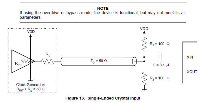
(1) If single-ended LVCMOS input is to be connected to the primary input pin, then 
which mode is to be selected through selection pins (00(primary input mode) or 
11(XTAL bypass mode))? 

(2) If selection mode is 00, then can the secondary input pins and Xtal pins (both Xin and Xout) be left floating? 

(3) If selection mode is 11, then can the primary and secondary input pins be left floating?

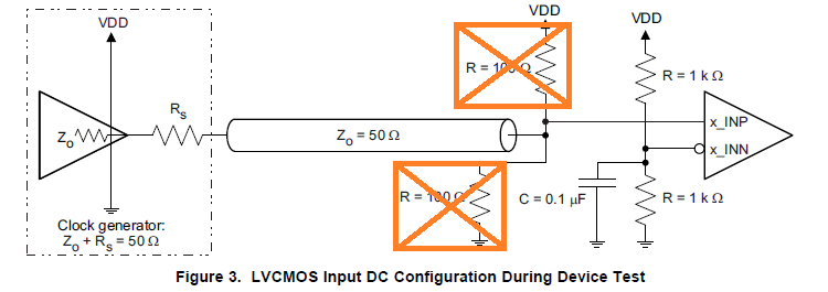
(4)  If the single- ended LVCMOS input is connected to primary input pin, In that case what should be the termination scheme for the PRI_INN, SEC_INP, SEC_INN and XTAL pins ?

(5) For LVCMOS configuration Pull up and down resistor is added for both PRI_INP and PRI_INN in the datasheet. Please explain the reason for doing so. Can they be avoided ?

  • Hi Megha,

    To input a LVCMOS clock  to CDCLVC1310,

    (1) All modes could accept the single end LVCMOS input. Considering performance, 00 and 01 is preferred.

    00 PRI_IN: DC couple. Refer to below Figure 3, but 100 ohm pull-up/pull-down resistors are not required. Notice we need a external bias on pin PRI_INN.

    01 SEC_IN: DC couple, it is similar as 00.

    10 XTAL or overdrive : Must be AC couple. Refer to below Figure 13

    11 XTAL bypass: DC couple. Figure 13 C= 0.1uF should be short.

    ---------------------

    (2) Yes. If selection mode is 00,  the secondary input pins and Xtal pins (both Xin and Xout) can be left floating.

    (3) Yes. All unused pins like x_INP, x_INN, XOUT could be floated.

    (4) Had answered above.

    (5) Pull up and pull down with 100 Ohm resistors: achieve bias voltage VDD/2, and achieve matched terminal load 50 Ohm. They could be ignored in Figure 3.

    Pull up and pull with 1kOhm resistors: acheive bias voltage VDD/2. They can't be ignored in Figure 3.

    Regards,

    Shawn

  • Thanks Shawn. It resolved the issue.