This thread has been locked.
If you have a related question, please click the "Ask a related question" button in the top right corner. The newly created question will be automatically linked to this question.
Hello,
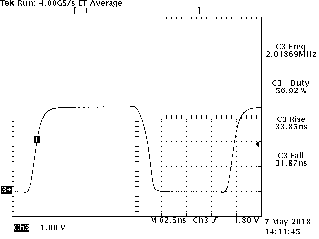
I am using LMC555 in astable configuration to generate a 2MHz square wave. However, I observed that the maximum I am able to go is approximately 1.6 Mhz, with a very low (~50pf) timing capacitor.
I am working at 3.3V and the output sees a maximum load capacitance of 10nf. I have made the circuit on pcb (used a bypass cap across Vcc and Gnd).
I want it to know whether at 3.3V with light capacitive load, the IC will be able to generate a 2Mhz wave?
Also, please point out if you see any particular issue why am I not getting a frequency output of 2Mhz.
Thank you for your reply.
I was using RA= 1.5 k and RB = 2.7K, after setting up the circuit as shown in the data sheet, I am indeed getting a 2Mhz squarewave. However, I find that there is some slewrate issue near sharp high transitions.
if I use the circuit config mentioned in figure 2 for 2 Mhz with precision ressitors, will I be able to get relatively accurate frequency (say within +/- 50ppm or so).
If not, what will you suggest as an alternative. I was also looking at using a crystal along with TI's crystal oscillator driver as an alternative.
Oh!
Can you tell me the resistor values you used?
The source may have ripple! I will try with a battery supply and post here.
Hmm, I see.
I am making a pcb for both 555 and Crsytal. I am using a crystal along with SN74LVC1GX04 (crystal oscillator driver), works fine.
By the way, I also used the same crystal oscillator driver in another project which required a 20Mhz clock, worked flawlessly.
I will post the results of the 555 frequency once I am done. Thank you for your help!