Part Number: LMX2571EVM
Other Parts Discussed in Thread: LMX2571, USB2ANY
Hello!
I am using a micro-controller to interface with an LMX2571EVM. My code for LMX2571 register access seem to be working just fine.
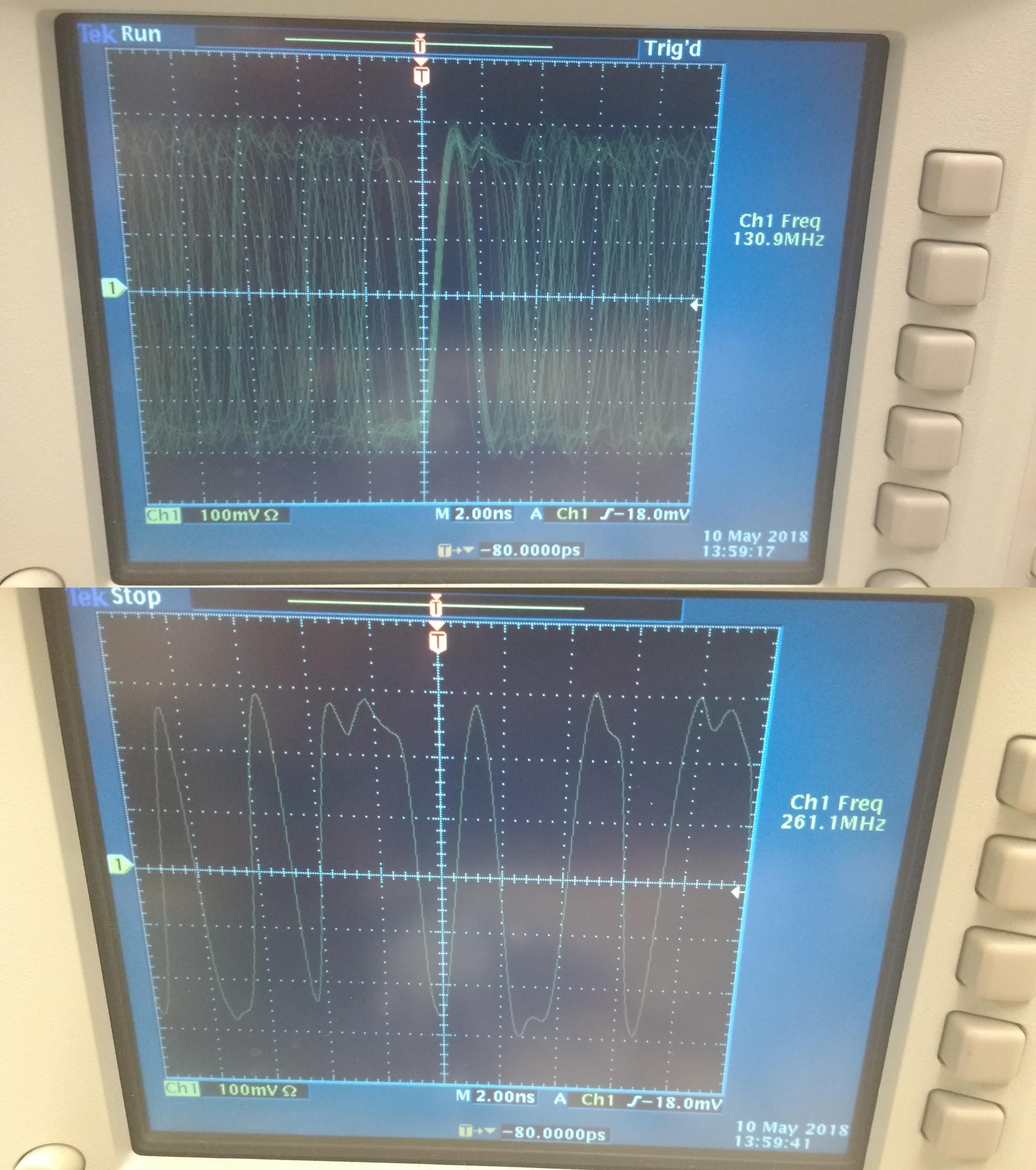
When I try to start up (initialize) the LMX2571 by programming it for the first time after a reset, it gives me an unstable output waveform. I read all the registers afterwards to ensure that they were programmed correctly.
When I use CodeLoader4 and USB2ANY interface to initialize LMX2571 with the same settings after a reset, the PLL behaves perfectly. Afterwards, I read all the registers again with the micro-controller to ensure that they were programmed the same way as previously.
To eliminate any possible differences between the above two cases, I used the micro-controller as an SPI slave to read the data output of USB2ANY during initialization. In addition, I used an oscilloscope to check the approximate baud rate and the average delay between consecutive USB2ANY register access events. I then used the exactly same data, the same register access order and similar timing settings to initialize LMX2571 with the micro-controller but still ended up with the unstable output.
If I initialize LMX2571 with CodeLoade4 and USB2ANY first and then proceed to control LMX2571 with the micro-controller (change the loop divider value, output power levels, etc.), everything works perfectly.
In summary, I used CodeLoader4 and USB2ANY as a reference and ensured that the micro-controller does everything in the same way during initialization but still ended up with the crazy output waveform. I have no idea of what is causing the difference and why the PLL does not seem to start up properly. I was wondering if you have any suggestions?
Please find the initialization settings below. The data stream is the same for USB2Any and the micro-controller. A figure of the unstable output waveform is also attached.
Best regards, Tuomas
~~~
reset:
R18 0x5087
R17 0x7A11
R2 0x5087
R1 0x7A11
R0 0x22C3
initialize:
R60 0xA000
R58 0x8C00
R53 0x7806
R47 0x0000
R42 0x0210
R41 0x0810
R40 0x101C
R39 0x11F3
R35 0x0C83
R34 0x1803
R33 0x0000
R32 0x0000
R31 0x0000
R30 0x0000
R29 0x0000
R28 0x0000
R27 0x0000
R26 0x0000
R25 0x0000
R24 0x0408
R23 0x0084
R22 0x8584
R21 0x0101
R20 0x301B
R19 0x1200
R18 0x5087
R17 0x7A11
R16 0x0000
R15 0x0000
R14 0x0000
R13 0x0000
R12 0x0000
R11 0x0000
R10 0x0000
R9 0x0000
R8 0x0408
R7 0x0084
R6 0x8584
R5 0x0101
R4 0x3020
R3 0x1200
R2 0x5087
R1 0x7A11
R0 0x02C3