This thread has been locked.

If you have a related question, please click the "Ask a related question" button in the top right corner. The newly created question will be automatically linked to this question.

LMX2572: High phase noise of the output signal

Part Number: LMX2572
Other Parts Discussed in Thread: LMX2594, , LMK00105, LMX2571

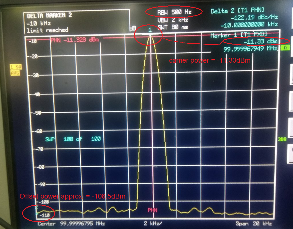
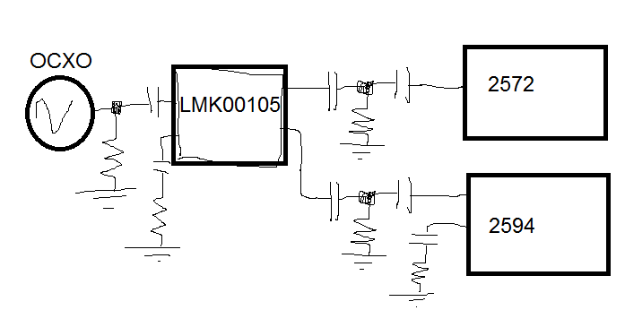
On the custom board, I use the LMX2572 and LMX2594 synthesizers to synthesize the frequencies 4600 - 4800 MHz (LMX2572) and the frequencies 6300 - 6500 MHz (LMX2594). The problem is that the LMX2572 synthesizer at frequencies 4600-4800 MHz has a high phase noise level at 10 kHz and 100 kHz (-90 dBc and 94 dBc, respectively).
At the LMX2594, the frequencies 6300 - 6500 MHz (12600 - 13000 MHz divided by 2) are not captured at all, rather they are captured, but at the output one can see the "palisade" from the harmonics of other frequencies, although, for example, the frequency is 7350 MHz (14700 MHz divided 2) is captured without problems, but the noise is also at 10 kHz and 100 kHz higher than the simulated values.
Maybe it's the board of course, but perhaps you will have some comments on the schematic and topolgy.

 LMX2572 PLL SIM frequency 4600 MHz  LMX2572 schematic & topology  LMX2594 PLL SIM frequency 6300 MHz

 LMX2594 schematic & topology  Power schematic if neededLMX2572 4600MHz 10kHzLMX2572 4600MHz 100kHzLMX2594 6300MHz

//LMX2572
C149, C157, C160, C184, C189 - GCM188R71E105KA64 (1 uF)
C151, C153, C166, C167, C169,  C186, C188 - GCM155R71H104KE02 (100 nF)
C150 - GCM1555C1H470JZ13 (47 pF)
C155, C162, C163, C165, C173, C183, C187 - GCM31CR71C106KA64 (10 uF)
C164 - GRM188R71H473KA61 (47 nF)
C168 - GCM1555C1H151JA16 (150 pF)
C170 - GRM155R71H152KA01 (1.5 nF)
C179, C180, C185 - GCM1555C1H101JA16 (100 pF)
C191 - GCM1555C1H3R0CA16 (3 pF)
L41 - B82496C3180J000 (18 nH)
R90, R91, R99, R100, R105 - CR0402-FX-49R9 (50 Ohm)
R92 - CR0402-FX-47R0 (47 Ohm)
R93 - CR0402-FX-3600 (360 Ohm)
R94 - CR0402-FX-27R0 (27 Ohm)
R95, R96, R98, R104 - CR0402-FX-1001 (1 kOhm)
R97, R101, R102 - CR0402-J/-000 (0 Ohm)
R103 - CR0402-FX-1002 (10 kOhm)

//LMX2594
C4 - GRM1555C1H680JZ01 (68 pF)
C7, C10, C49, C53 - GCM155R71H104KE02 (100 nF)  
C2, C13, C17, C25,C29, C31, C46, C55 - GCM188R71E105KA64 (1 uF)
C11, C20, C21, C23, C35, C45, C52  - GCM31CR71C106KA64 (10 uF)
C22 - GRM188R71H473KA61 (47 nF)
C30 - GRM1555C1H391JA01 (390 pF)
C33 - GRM155R71H332KA01 (3,3 nF)
C37, C39, C48 - GCM1555C1H101JA16 (100 pF)
C58 - GCM1555C1H1R0CA16 (2 pF)
L42 - B82496C3279Z000 (2,7 nH)
R2, R5, R24, R25, R35 - CR0402-FX-49R9 (49,9 Ohm)
R6 - CR0402-FX-15R0 (15 Ohm)
R8 - CR0402-FX-1200 (120 Ohm)
R14 - CR0402-FX-33R0 (33 Ohm)
R15, R16, R21, R34 - CR0402-FX-1001 (1 kOhm)
R18, R28, R29 - CR0402-J/-000 (0 Ohm)
R32 - CR0402-FX-1002 (10 kOhm)

// Power
C192, C193, C305, C306 - AVXTPSB336K016R0350 (33 uF)
C194, C195, C211, C213, C309, C312, C323, C325 - GCM188R71E105KA64 (100 nF)
C313 - GCM155R71H681KA37 (680 pF)
C314, C315 - GCM32EC71H106KA01 (10 uF)
C216, C217, C327, C328 - GRM32ER61C476KE15 (47 uF)
C331 - GRM21BR71E684KA88 (680 nF)
C334 - GRM32ER71C226ME18 (22 uF)
C208, C210, C318, C322 - GCM1555C1H102JA16 (1 nF)
DA16, DA17, DA34, DA35 - ADM7170ACPZ-3.3
DA36 - LT3680IDD#PBF
L38 - MOS6020-682ML (6,8 uH)
R152, R154 - RL73K3AR10JTG (0,1 Ohm)
R157, R159 - CR0603-FX-1502 (15 kOhm)
R163 - CR0603-FX-1002 (10 kOhm)
R164 - CR0603-FX-3742 (37,4 Ohm)
VD3 - MBRA340T3G
Z26, Z27, Z47, Z48 - NFM21HC105R1C3

  • Hi Andrey,

    regarding the phase noise of LMX2572, my test result is similar to simulation. However, I see your measured output power is just -14dBm, is this intentional?
    Can you put your test equipment to phase noise mode? Will the measurement in this mode agree with the spectrum mode? I think the spectrum result is not quite right, the noise floor is high.

    For LMX2594, RFoutAM should also be pull-up with an inductor.

    For both devices, the unused RFoutB pins can be left floating.
  • Hi Noel,

    Unfortunately, the phase noise measurement mode in my spectrum analyzer (Rohde & Schwartz FSU 46) does not. Therefore only so.
    Regarding power: on my board the signal from the synthesizer is mixed with another signal for upconversion, so a direct measurement is impossible (there is no technological connector for measuring the signal parameters from the synthesizer on the board). To measure the signal from the output of the synthesizer, a homemade probe was made which was placed on the microstrips after the output capacitor. The signal loss in this way is about 16 dB, which is not so important since the phase noise does not increase.

    Thank you for the remark about the termination of the RFoutAM output! Did not really notice this in the datasheet. Now the LMX2594 finally got a signal of 6300 MHz without harmonics of other frequencies. However, the phase noise of this signal is also high: at 10 kHz I see -96 dBc, at 100 kHz -104 dBc.

    It seems that something in my board produces low-frequency noise, but I can not understand what. I tried to supply power directly to the linear regulators (3.8 V on the ADM7170) bypassing the LT3680(swtiching regulator), suggesting that it was the LT3680 that could give such a low-frequency noise, but nothing has changed. Phase noise remained the same.

    Any idea what might be the problem?

    If this is useful:
    my generator at 100 MHz has:
    10 Hz        - 95 dBc
    100 Hz      - 125 dBc
    1 kHz         - 153 dBc
    10 kHz        - 165 dBc
    100 kHz      - 168 dBc

    On my board there are also: PIC32MZ microcontroller (operates at 120 MHz), 16 MHz crystal oscillator, 10 bit DAC (AD5320), CAN module (1 MegaBaud rate).

  • Hi Andrey,

    Your generator phase noise is very good, is it a XO or a bench top equipment? If it is a signal generator, could you make it output at around 4GHz and then measure the phase noise? Alternatively, could you make LMX output 100MHz and then check the phase noise again? I want to make sure this is not a test equipment issue.
    In the layout, how is the Vtune trace (after the third pole) routed to the fourth pole? Did you make good isolation or shield to this trace?
  • Hi Noel,

    I use OCXO. 

    OCXO spec

    The route from the third to the fourth pole is made through the 7 layer of the board. The next 8 layer is the earth. On the 6th layer above the track, the third -> the fourth pole is the PLL_3.3VA signal - it is the stabilized analog voltage from the output of the LDO ADM7170 (output noise is 6 μV).

    CPOUT-topologyCross CPOUT & VTUNE topologyVTUNE topology

    Phase noise of the frequency of 100 MHz from the output of the synthesizer:

    Phase noise 1kHzPhase noise 10kHzPhase noise 100 kHzPhase noise 1 MHz

  • And one more question:
    What should be the reference level at the OSC input? For the LMX2572 and LMX2594 synthesizer? They are the same? In the specification it is written that the signal should have a fast rise front, but be of small amplitude.
    My signal is 100 MHz at the OSC input:

    Signal of OSC input

    Is it a normal amplitude or more?

    And the signal is 100 MHz on the output of the RFOUTA (the signal is distorted apparently due to the second and third harms):

    Signal of output RFOUTA

  • Hi Andrey,

    The amplitude of your 100MHz OCXO is fine, although it is distorted.

    I still think that the phase noise "problem" is a measurement error because you were using a specAn to "calculate" the phase noise. As such, your measurement will depend on the amplitude of the carrier.

    For example,

    So the calculated phase noise = (Offset power - carrier power) - 10log(RBW) = -122.16dBc/Hz.

    If you can make a direct measurement, then the carrier power will be higher and therefore the phase noise will be better.

  • We have already measured the spectrum analyzer's own noises, it can not be better than result. Even if I amplify to +10 dBm, the phase noise will not be better. This is limitation of the dynamic range of the spectrum analyzer. 

    Finally, I got the agilent N9000 spectrum analyzer with the function of measuring phase noise. And measured the phase noise of the reference signal:

    Reference phase noise

    Here we also see SSB phase noise of the spectrum analyzer.

    In addition, in one of my past projects, I already used exactly the same OCXO to generate a frequency of 6300 MHz using the HMC700LP4 chip and the HMC466LP4 VCO (PFD 50 MHz) and the phase noise was as follows:

    HMC700LP4 & HMC466LP4 frequency 6300 MHz

    So the generator is checked in other projects, I do not think that the reason is in it.

    In the figure in the last message, i showed that the amplitude of the reference signal at the input of the synthesizer is about 450 mV, while the phase noise at 4600 MHz (LMX2572) is at 10 kHz -90 dBc, at 100 kHz -93 dBc. Yesterday, I increased the reference signal level to the synthesizer to check what would happen:

    Amplitude reference signal

    And i was very suprised when the phase noise became better:

    LMX2572 4600MHz Phase Noise

  • How does the matching of 50 Ohm line with a high-impedance input work? should not most of the power be reflected? can there be a case in this?
  • Hi Andrey,

    Are you sharing the OCXO output to both LMX devices?
    Could you try simply AC-couple the OCXO output to LMX2572? Also measure the waveform at the 50ohm shunt resistor? I expect the waveform will not get any distortion. 

  • This is my scheme of the path of the reference signal:

    Reference signal path

    Now shunting resistors of 50 Ohm on the board are not installed, instead of them bit IPBUF_TERM in register 5 is switched on. But I tried to install external shunting resistors - nothing changes.

    The signal is distorted because the amplifier is in saturation.

    The previous oscillogram was taken from the point after the amplifier and in front of the capacitor (noted in the figure).

  • Hi Andrey,
    OK, them please try bypassing the "power splitter", simply connect the OCXO to LMX2572 and see what happen. If the phase noise get improved, then may be you need to tweak the splitter until you get good phase noise again or you may consider to use a clock buffer like LMK00105.
  • I bypassed the splitter by connecting the OCXO output to the amplifier input. Vpp of the reference frequency was 3.45 V.

    Phase noise became even better.

    But, as follows from the specification, this level should damage the device? LMX2572 is possible and not, but when you apply this level to the LMX2594 this will happen. Or I'm wrong?

    Moreover, unless the device should not give out good phase noises already at 0.2Vpp. I understand the specification so that when I feed at least 0.2Vpp to the OSCin, I must get the calculated phase noise on the output.

    LMK00105 is a good thing, but I do not understand how it can help. I have not 5 devices, but only 2. Why complicate the scheme.

  • Hi Andrey,

    What I was trying to see was with OCXO output connect to LMX2571 input directly(as shown in the pic in the previous post). The output power of the OCXO is 7dBm, which is about 1Vpp swing into a 50 ohm load. This experiment was trying to figure out whether the bad phase noise was due to the splitter and amplifiers. If this is the case and if you don't want to spend time to find out the sweet spot of the splitter and amplifiers, I suggest use a clock buffer, which would simplify the design and provide high quality clocks for the LMX devices.

    LMK00105 can take the sinewave from the OCXO and then outputs square wave CMOS level clocks. With 50ohms load, the voltage swing of the buffer is less than 2Vpp, so it will not hurt the LMX devices. The unused outputs could be left open. TI do have some clock buffers with two outputs but unfortunately, they do not support 100MHz.

  • Hi Noel,
    Well, I understand you. I connected the OCXO output to the LMX2572 input directly. Phase noise became worse and amounted to 10 kHz -86 dBc, 100 kHz -89 dBc.
    But I do not understand the other, if it's a noisy reference frequency, why is the phase noise getting better when the reference signal is increased (via an amplifier)?
  • Andrey,
    For the LMX2594 and LMX2572, the PLL phase noise is impacted by the slew rate of the input signal. In general, if the slew rate is too low, the PLL phase noise is degraded.

    Regards,
    Dean