This thread has been locked.

If you have a related question, please click the "Ask a related question" button in the top right corner. The newly created question will be automatically linked to this question.

LMX2581: PLL locking and phase noise issues

Part Number: LMX2581
Other Parts Discussed in Thread: LP2985, CODELOADER, LMX2541, , LMX2531

Dear Sir, Good Morning.

I am facing problems  locking issues with LMX 2581. I want to use it as a synthesizer for generating  multiple  freq. (one at a time) 950 MHz, 990 MHz, 1030 MHz, 1070 MHz & 1110 MHz using 20 MHz Oscillator input. The RF output  setting of 950 MHz  freq. comes 948.62 MHz that is also not locked . I have used the the 3 LDO for supply of LMX 2581 (LP2985) and presently for testing i am giving 20 MHz from signal generator  around +     3 dBm at Oscillator input. The phase noise performance is also very bad. I have checked the circuit as per your evaluation Board. please help

  • LB,

    Thank you for prividing all these details.  In general, I see some ways to optimize things, but no obvious errors to make the PLL unlock.

    I'm not sure the issue, but it seems to me that it looks like the VCO calibration is choosing the wrong frequency band.  The VCO calibration chooses the VCO_CAPCODE.  If it were off, you would get the wrong frequency.  You might want to measure the tuning voltage and verify that it is forced the rail.  The things that might cause this are:

    1.  Issue at OSCin Input

    20 MHz is lower frequency and if this is a sine wave, it could have  slow slew rate.  If there was any sort of sensitivity problem during calibration, the VCO could get stuck to a frequency band that is too low. If there is a slow slew rate and there is any sort of noise during calibration, it could cause a miscount and lead the PLL to the wrong frequency band.  I don't know your resistor values in your pad, but if you could increase slew rate, then this would help.  Also, slow slew rate can cause PLL phase noise degradation, and I think you mentioned something about high noise. 

    2.  Programming/Bias Caps

    There are 22 uF bias capacitors.  If you are coming out of cold power up these take time to charge up.  Also realize that if you just program R15 to R0 and then you need to program the R0 register one more time.  The voltage at pin 18 also needs to settle.  If you find that there is unlock the first time, but programming the device multiple times resolves the problem, it points to this.

    Also, regarding the information you provided, I also have some comments ...

    CodeLoader PLL Tab and Bits/Pins Tab:

    -  I see nothing that would cause the PLL to not lock.   From a performance standpoint, it looks like your reduced fraction always has a denominator of 6 or less, so I would suggest changing the fractional denominator to 2 and use a 1st order modulator with no dithering for optimal spur performance.  Also, this is optimal for phase noise.

    CodeLoader Regiseters Tab:

    -  I see nothing wrong.  There are some test registers that are critical and these are set right.

    General CodeLoader Comments:

    -  I don't think it will solve this issue, but I encourage you to use TICSPro.  It is basically an upgraded form of CodeLoader

    Schematic:

    -  For RFoutA, you don't have to spend valuable board real estate to route an output that you don't use.  You can just power down and float the pins.

    Regards,
    Dean

  • Dear Sir,
    Thank you very much for your valuable suggestion. I am trying to implement your suggestion and get back to you.

    Reagrds
    L B Dube
  • Dear Sir,
    1.
    How Can I increase the slew Rate of the Oscillator input. For testing of this card I provided the Osillilator input using Agilent Signal generator which is very stable (Although in my Actual Card I used the TCXO from Rakon Part No CFPT-9007-EX-3A-LF used Before that I also run no of cards using LMX2541 and this TCXO) ) . Actually I measured the Power input at Oscillator input pin in LMX2581 it is around 2-3 dBm. Sensitivity level of this IC as per the data sheet is -3.9 dBm so it should work well for +3 dBm input Perfectly.

    2. VCO_CAPCODE=128 i used and I will measure the tuning voltage and get back to you .

    3.I programmed the Device 2-3 times but it does not lock.

    4. You suggested N=47 and Fnum=1000000 Fden=2000000 for output frequency of 1900 MHz I will implement and get back to you.

    5. I have programmed the device using DB-9 connector (used LE, CLK, DATA and Ground) with codeloader 4 Now I try to run this with TICSPRO and get back to you.


    Regards
    L B Dube
  • Hi Dube,

    I used your setting and I can make it lock also using a sigGen as the reference clock.
    Are your sigGen and sepcAn using the same 10MHz reference clock?
  • Dear Sir,
    1. I checked the Ref Clock of Spectrum Analyser and Signal Genertor is 10 MHz. But it is not locking actually I measured 950 MHz it gives around 949 Mhz I placed a peak marker also. that Peak marker is not stable at peak it chages that means PLL is not locked.
    2. Further I measured the Vtune Voltage at C29 pin it is not correct. it is coming 3.147 V but as per data sheet it should be 1.4 V.
    3. I tried the N=47, Fnum=1000000 & Fden=2000000 and Frac_order = First order but it does not help also.
    4. I placed L3=18 nH (simple SMD inductor) at VCCBUF pin . Is it correct or should i place ferrire bead of 120 ohm.
    Please provide your suggestion how can I Lock my PLL circuit.


    Regards:
    LBdube
  • LBdube,

    1&2. I note that you measure 3.147 tuning voltage and you are measuring 949 MHz when you expect 950 MHz; 2 MHz low at the VCO frequency. Realize that this device has a negative tuning coefficient VCO and that the tuning range is divided into many different frequency bands. So this looks like the VCO has likely chosen the correct frequency band during calibration, but now it feels that it wants to push the VCO frequency lower and has run out of headroom. I think that the most likely issue is with the 10 MHz input reference. If there is any way to increase the signal generator power or signal generator frequency (for diagnostic purposes), that would be helpful to verify this. Also, the LMX2581 allows the user to see the output of the R divider through the MUXout pin. This could be a helpful diagnostic as it tells you the actual divided down values that the part perceives it sees, which is more complete confirmation. Also, ensure that the reference is AC coupled as DC coupling could cause input sensitivity issues.

    3. OK, sound like it's not a fractional issue
    4. The ferrite bead is not so critical; you can put 0 ohms there. The ferrite bead may improve the phase detector spurs a few dB, but as you are having difficulty getting the part to lock, it's best to reduce sources of uncertainty. The 18 nH is likely more dependable than the ferrite bead; I have seen ferrite beads sometimes cause stability issues.

    Also, make sure that you calibrate the VCO last. For instance, if you use the output divider, make sure that you calibrate with this output divider. The output load could introduce a small VCO frequency shift and cause the VCO to choose a different band. Understand that the LMX2581 has 4 VCO cores and each core has 256 different bands, so that's 1024 bands total.

    Regards,
    Dean
  • Dear Sir,

                       I appreciate your continuous support. I tried to implement your suggestions.

    1. I Synchronize the Signal generator and Spectrum anayser for same Ref Source at 10 MHz This I have  achieved by using 10 MHz output from signal generator and given as a external ref input to Spectrum analyzer.

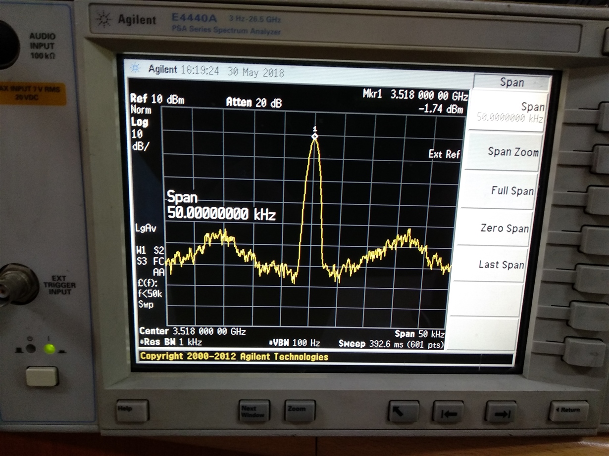
    2.    I changed the Oscillator Input frequency and power   and tried to lock the PLO at some other frequency exp-3518 MHz (which is required for my other application) . PLO locks and gives stable frequency. Although phase noise is not very good. Phase noise gets worse at 16-17 KHz away from the carrier frequency of 3518 MHz. This is shown in 3518_sa.jpg file. how can i improve my phase noise.

    Further I tried to generate 3518 MHz by using 20 MHz  Oscillator but it does not locks. output peaks  frerquency varies .

    3. I tried to generate the 950 MHz by using the 100 MHz Oscillator Source but output does not locks I sent the video of this one. File:950_vd

    Please suggest how can i make stable.

    4. I selected the LD for R/2 and N/2 respectively and checked LD signal it gives 50 MHz stable output this mens it is behaving correct.

    Regards:

    LBDube

  • LBDube,

    From the software settings, I would say this:
    1. If the fraction you want is 1/2, just express this as 1/2 and use the 1st order modulator. This is optimal for spurs and phase noise.
    2. TICSPro has an upgraded GUI and more visual feedback for the user to highlight issues. I encourage you to use this one.


    It also seems that when you change the input reference, you are also changing the phase detector frequency, and this is introducing another unknown into a situation where there are already unknowns. I would suggest pick a fixed phase detector frequency, say 20 MHz, as this is what the board was designed for. Then for 10 MHz input, use the OSC_2X to double 10 MHz to 20. For the 20 MHz, go straight in. For 100 MHz, divide by 5. In this way, the issue can be better isolated. If you change the phase detector frequency from 20 MHz to 100 MHz, you change the loop bandwidth and loop dynamics, so this is another unknown. Also realize that when the input frequency goes above 64 MHz, OSC_FREQ word needs to be increased.

    Also, I see that you start with VCO_SEL=4 and one of the frequencies of interest you have is in the range of VCO4. Be aware of this note in the datasheet on page 19.
    "A good starting point is to set VCO_SEL = 2 for VCO 3 and set VCO_SEL_MODE = 1 to start at the selected
    core. If there is the potential of switching the VCO from a frequency above 3 GHz directly to a frequency below
    2.2 GHz, VCO_SEL_MODE can not be set to 0. In this case, VCO_SEL_MODE can still be set to 1 to select a
    starting core, but the starting core specified by VCO_SEL can not be VCO 4"

    Regards,
    Dean
  • Dear Sir,
    Good Morning.

    Can you provide how to connect the TICSpro to USB.
    Presently I am programming the my Lmx2581 using codeloader4 and i have connected the LE, CLK, Data and GND to from my PCB board to DB25 connector (parral Port 25 Pin Connector) at pin no. 3, 4 , 2 and GND at pin 25 as per code coder connection.
    Can you please tell me CLK, Data and LE outputs from my PCB Board where to be mapped in (pin nos) USB or some converter board i need to use.
    please tell so that i can proceed with TICSpro.

    Regards
    LBdube
  • Dear Sir,

                   I tried a lot to lock the output  frequency at 950 MHz and at 3518 MHz using 20 MHz Oscillator input and same 20 MHz as a Phase Detector frequency but it does not lock even i measured the lock voltage it is 0 V .

    1. For 950 MHz output goes around 949 or at 951 MHz and out peak oscillates i checked the Mux out  by setting MUX_out_select =R/4 output comes at 5MHz stable out put and in second case i set the MUX_out_Select =N/4 then output is stable locked at 5.02 MHz  (Although it should be 5 MHz).

    2. I tried to change the Oscillator input power level from -2 dBm to  5 dBm (Recommended -4 dBm to +8 dBm in data sheet) but it does not lock.

    3. I  tried the make  setting of VCO core as you recommended  VCO3 and VCO_mode=1 as  you see in attached file but in any condition it does not lock.

    4. I tried to lock at 3518 MHz using 20 MHz phase detector  and 20 MHz Oscillator input  it does not lock.

    5. One more strange thing I notice under open condition I measured the VCC_frac=4.2 V  (in my circuit i measured this  by opening R26 one side towards the VCC_frac the voltage=4.2 V and another side  i applied it is 3.3V (coming as 3.3V_3)) why this 4.3 voltage appears.

    I think there is some problem with this Device LMX2581 in locking issues .Before two months I also made two cards using LMX2581 these also having locking issue. I request you to check this my realizing this  PCB board using LMX 2581 and check whether you are able to  lock or not.

    or check the eval board of this device some problem with nearby components values in your evaluation board. I tested  other LMX synthesizer like LMX 2541 and LMX2531. But i have faced any problem in locking.

    This is not only my problem but some one else on this community also raised the same locking issue problem with LMX2581 so please for our designers satisfaction please check or if you find something wrong  then please check and corrective decision


    950_MHz.docx .

    Regards

    LB Dube

  • LB Dube,

    I took the LMX2581 EVM and lock to both 950 and 3514 MHz with both 20 MHz and 100 MHz input; no problems. You have done several experiments regarding the OSCillator input and this has not gone anywhere.

    Now I am suspicious of the hardware because:
    1. RFoutA with two pull-down resistors to ground. But these are supposed to be pulled to Vcc. In some of the files you sent, you have RFoutA powered up. As the output buffers consume a lot of current, this seems like it could be problematic. In general, it would be best to simply remove the two pull down resistors (looks like R8 and R9 on schematic, but hard to read). Our power supply pins are connected by an ESD diode ring, which means that if you ground one power supply, it pulls down the others. Now RFoutA is not a power supply, but if you ground something that is expected to be pulled to Vcc, maybe this is an issue.
    2. For your experiment with VccFRAC, this pin typically draws < 1 mA, so I would not expect a large voltage drop accross the resistor. Maybe when you open the resistor, perhaps this pin is being powered through the ESD diode ring. I would have expected for it to be more like 0.7 V below the other supplies though, not higher. Maybe internally, the VCO tank can run at higher voltages than 3.3. You are measuring higher than 3.3V and having problems with the VCO, so it is acting like something is getting sorted. Add this to having RFoutA grounded, and maybe it could be pointing to an issue.
    3. For the power supply pins, I can't read the series resistor values. Section 10.1 on page 47 of the datasheet gives an idea of current consumption by pin, so you can get an idea of the voltage drop.

    Regards,
    Dean