This thread has been locked.

If you have a related question, please click the "Ask a related question" button in the top right corner. The newly created question will be automatically linked to this question.

BQ32000: Write and read protocol realization

Part Number: BQ32000
Other Parts Discussed in Thread: TMS320F28027

Hi,

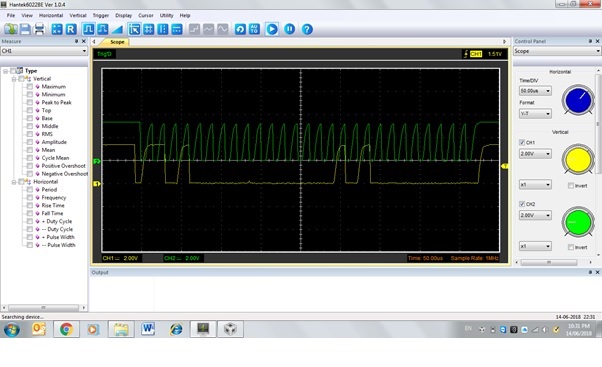
   I have designed a RTC circuit using BQ32000. TMS320F28027 is  writing and reading real time  once everyday. I want to know from an experienced person in BQ32000, what are the probable mistakes one can make in the reading and writing protocol realization? Please share your thoughts.

Regards,

Mahesh K.R. 

  • Hi Mahesh,

    I see that you have been interacting with another engineer in another thread. Could you elaborate on what you are looking for?
    e2e.ti.com/.../695428

    Assuming your I2C communication is implemented properly, one important detail to be aware of is that the device will not communicate over I2C if the main power supply is less than the backup power supply (VCC < VBACK). See datasheet section 8.2.2.1 for more information.

    Kind regards,
    Lane

  • Hi Lane,
    In my circuit the Vcc and Vback both were 3.3V. Now I changed to VCC=3.3 and Vback to 2.6V. Still some issues. Not writing properly , I checked the interrupt, after writing, No signals coming out.

    I want to clarify the slave address (BQ32000). The data sheet says, 11010000b for write commands, that means 0xD0 and 11010001b for read commands, that means 0xD1. Am I right? or if we consider 7 bit operation 11010000b for write commands, that means 0x68 and 11010001b for read commands, that means 0x68. Please clarify.
    Regards,
    Mahesh K.R.
  • Hi Mahesh,

    Yes, this seems to be the correct address for 8-bit operation based on the datasheet, but I don't have a board to check this on. However, I will try to help you debug. I recommend to begin by checking your I2C waveforms (Make sure that you are correctly following the I2C protocol outlined in datasheet section 7.5.1):

    • Do you have the appropriate pullup resistors on the SDA and SCL lines?
    • Are you properly sending START and STOP (high-to-low and low-to-high transition while clock is high, respectively)
    • Are you receiving an ACK after writing the device address, register address, and register data?

    I also want to provide a link to another post in the forum that may be related to your issue (excerpt and link below);

    "The BQ32000 has an internal buffer which is updated with the RTC counter data every second. The user only has access to this internal buffer and not the real time keeping counters. If the user is in the process of reading the time from the internal buffer, the 1 second update is stopped until the read is complete. The internal buffer is then updated immediately after the read is complete (instead of waiting for the next 1 second update).As a result the user will never see a rollover condition while doing a read of the registers. I hope this answers your question."

    Related post:

    Kind regards,
    Lane

  • Hi Lane,

      Thank you very much for the support.

    Do you have the appropriate pullup resistors on the SDA and SCL lines?  - Yes 4.7K

    Are you properly sending START and STOP (high-to-low and low-to-high transition while clock is high, respectively)

    Are you receiving an ACK after writing the device address, register address, and register data?

    Write function and the SDA and SCL wave forms are given below. I am using 7 bit data. 

    void I2CA_WriteInit2()

    {

    EALLOW;

    // Setup number of bytes to send

    I2caRegs.I2CMDR.bit.MST = 1;

    I2caRegs.I2CMDR.bit.TRX = 1;

    I2caRegs.I2CCNT =0x02;

    I2caRegs.I2CMDR.bit.STT = 1;

    I2caRegs.I2CDXR = 0x01;

    I2caRegs.I2CDXR = 0x80;

    I2caRegs.I2CMDR.bit.STP = 1;

    EDIS;

    }

    Read function and its SDA-SCL wave forms are given below.

    void I2CA_ReadData1()
    {

    EALLOW;
    I2caRegs.I2CMDR.bit.MST = 1;
    I2caRegs.I2CMDR.bit.TRX = 1;
    I2caRegs.I2CCNT =0x01;
    I2caRegs.I2CMDR.bit.STT = 1;
    I2caRegs.I2CDXR = 0x00;
    I2caRegs.I2CMDR.bit.STP = 1;
    I2caRegs.I2CMDR.bit.TRX = 0;
    I2caRegs.I2CCNT =0x01;
    I2caRegs.I2CMDR.bit.STT = 1;
    Second= I2caRegs.I2CDRR;
    I2caRegs.I2CMDR.bit.STP = 1;
    EDIS;

    }

    Please review and give your thoughts.

    Regards,

    Mahesh K.R.

  • Mahesh,

    I can't give feedback on this and Lane is out of the office this week. I will forward this to him and maybe he can help.

    Regards,
    Dean