This thread has been locked.

If you have a related question, please click the "Ask a related question" button in the top right corner. The newly created question will be automatically linked to this question.

LMX2592: What parameter should we consider for lower error rate for communication equipment?

Part Number: LMX2592

Hello,

When we design PLL parameter for communication equipment, what parameter should we care about?

We are struggled LMX2592 design. The error rate doesn't reach the target.

I would like to know what parameter should be pay attention in general for error rate.

And also make the parameter of PLLatinum Sim.

The condition is below.

1) Reference clock is 120MHz.

2) Output frequency is 5940MHz.

3) VCO frequency is 5940MHz.

We would like to try the parameter then narrow down what parameter should be changed for improvement.

Best regards,

Toshihiro Watanabe

  •  Toshiro-san,

    Bit error rate is related to integrated phase noise.  Integrated phase noise has many interpretations, but they are all somewhat related.  If you design the filter for lowest jitter then this is optimal.

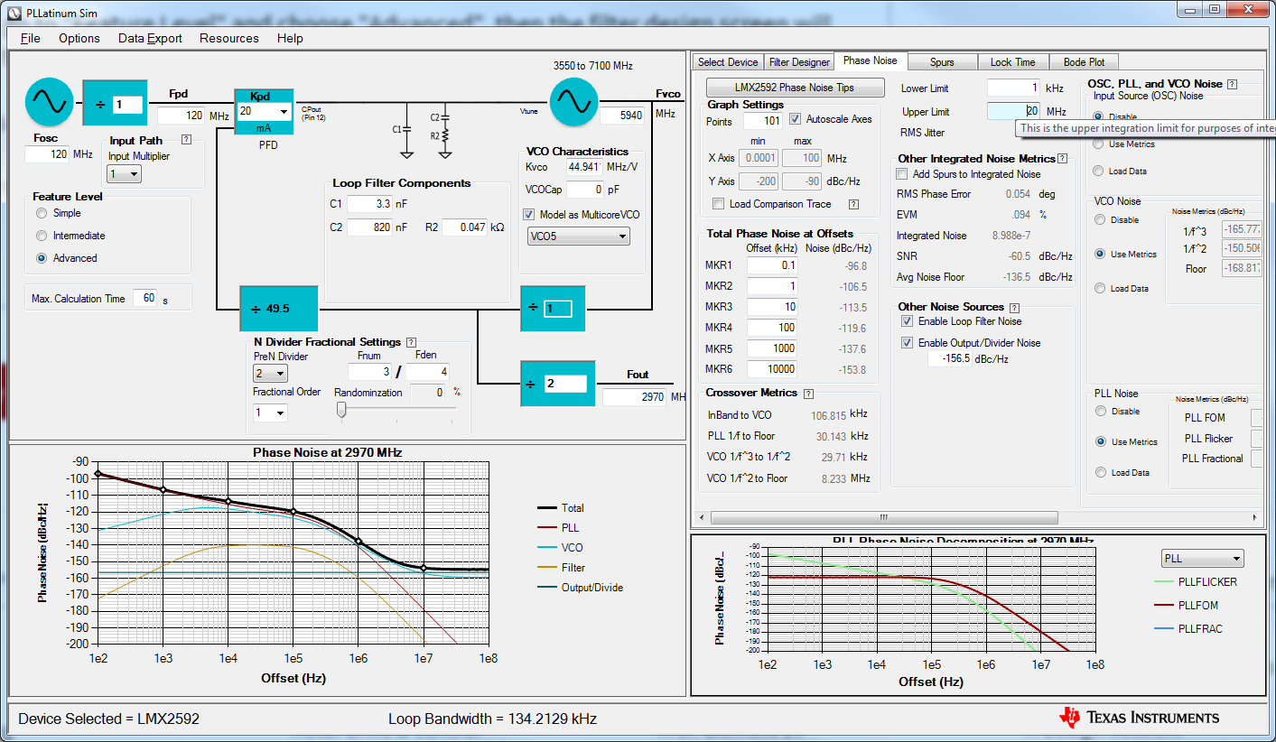
    If you go to "Feature Level" and choose "Advanced", then the filter design screen will show the filter optimizer that allows this.

    Here's the result I got when I tried, 50.8 fs.

    Regards,

    Dean

  • Hello Dean-san,

    Thank you for the design. We will try this.

    Would you review the attached PLLatinum configuration? This is optimized spur but the RMS jitter is to get similar number as the setting.

    PLLatinum_120Mref_5940MVCO_5940MVout_4order.zip

    We measured the error ratio by system but the result was not so good. The number of this condition was 2.77E-06. The target error rate is 7.00E-8. In our experience, lower spur is better result. We are not sure this trend is correct or not though.

    As the starting point from this result, I would like to review the setting is correct or not at first. Then I would like to know what we can do for reducing the error ratio.

    It would be helpful to advise us for the improvement.

    Best regards,

    Toshihiro Watanabe

  • Hello Dean-san,

    Error rate was 2.77E-06 in my configuration. The best error rate so far is 1.03E-07 in the customer configuration.

    The configuration is attached. Is it possible to imagine from the customer setting why the error rate was better?

    Bestconfiguretion_sofar.zip

    Best regards,

    Toshihiro Watanabe

  • Toshiro-san,

    I do not understand why better spur is better result. Your integration range is 1 kHz to 2 MHz, but if you use the 1st order modulator, the closest spur is 30 MHz offset. With 3rd order, it is 15 MHz away. Either way, it is out of this integration range. Now if the customer is not using this fraction and is using something else, like 3000000/4000001, then I would make more sense.

    What I am thinking is that perhaps there is a lot of fractional noise, or that maybe the input reference is much noisier than expected. I note in your simulation that the input reference noise is disabled. So if you chose a narrower loop bandwidth, this not only improves the spurs, but would help clean up the input reference.

    Regards,
    Dean