Other Parts Discussed in Thread: NE555
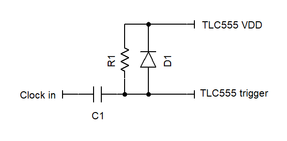
Hi, we've built a PWM circuit based on the example in the TLC555 data sheet (section 9.2.2), but can't get less than a 50% duty cycle.
We've a 500Hz square wave clock input to the Trigger, and the Threshold is fed from an RC network as you'd expect (3k resistor, 0.47uF capacitor).
We can vary the control voltage and get a change in the duty cycle, but the key fact is that when the clock is low, which causes the output to be set, the threshold input to reset the output does not take effect until the clock goes high, hence the minimum duty cycle is set by the 50% clock duty cycle.
This means that the graphs shown in figure 15 are not achievable in reality with the TLC555 if you're using a 50% clock, and I suspect that these were generated using a traditional 555 chip.
Can you confirm that this is a constraint when using the TLC555, and amend your data sheet to either have graphs that reflect the behaviour of the device, or at least a note detailing this fact more clearly, especially around the PWM example and the clock source.
Alex