This thread has been locked.

If you have a related question, please click the "Ask a related question" button in the top right corner. The newly created question will be automatically linked to this question.

What is the current consumed by TLC555 when the RESET pin is activated.

Other Parts Discussed in Thread: TLC555

Hi,

I have a customer who has the query given below:

What is the current consumed by TLC555 when the RESET pin is activated ?

I have a doubt if IDD is the same current that is consumed (or that flows through VDD) when RESET pin is activated.

Please help.


Thanks and Regards,

C.Pradeep

  • Hello Chiprad,

    The TLC555 operating current will be a function of how the timer is applied. Therefore, the specific current in astable, monostable, or reset mode, may be different by application.

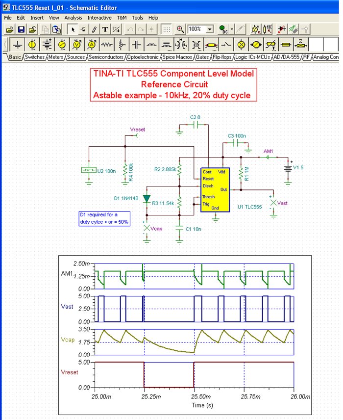
    We have a complete component-level simulation model for the TLC555 which allows us to simulate the operating current in applications. I selected our astable reference design circuit to compare the supply current while in the astable mode and then when interrupted by a reset. The reference circuit is shown below and a timing diagram displays the significant voltages and supply current in the circuit.

    During the time period of 25.25ms and 25.50ms Vreset, the voltage on the Reset pin, drops from 5V to 0V initiating a reset. You will note that during this period that the operating current, AM1, does not change. There may be some small change in the supply current but the plot may not provide enough resolution to readily observe it.

    Regards, Thomas

    PA - Linear Applications Engineering 

  • Hi Thomas,

    Many thanks for your explanation.

    You mean to say that current consumed depends on the mode it transits to RESET, is that so? If yes, then how to calculate current consumed in that case.  Please provide any reference to calculate the same.

    Please do let me know the value of current consumed when RESET pin is activated.


    Thanks and Regards,

    C.Pradeep


  • Hi Chitprad,

    The TLC555 operating current, like for many CMOS devices, will be somewhat dependent on the speed at which it switches. Also, supply voltage, the semiconductor processing variables, the external RC values, load current, etc, will all affect how much current the TLC555 consumes. Therefore, there isn't any equation that captures all the variables and allowing one to calculate the current. The operating current listed in the data-sheet is for a very specific condition. The example I provided and the resulting current where specifically for that particular astable application. That simulation indicated that the operating current did not change significantly when the RESET was activated.

    I recommend that you useour TLC555 TINA simulation model (or import the .txt version into another PSpice simulator) and modify the reference circuit to match your particular application circuit. There are reference circuits available on the TLC555 for both monostable and astable configurations. Use the transient analysis (select zero initial conditions in TINA) and monitor the supply current with, and without, the RESET being activated. Short of making the measurement with your actual circuit this should be the next best way to determine the current.

    Regards, Thomas

    PA - Linear Applications Engineering

  • Hi Thomas,

    Thanks a lot for the solution.

    Have a nice day.


    Regards,

    C.Pradeep