This thread has been locked.

If you have a related question, please click the "Ask a related question" button in the top right corner. The newly created question will be automatically linked to this question.

LMX2594: LMX2594 Consistent Calibration Time Across Large Frequency Sweep

Part Number: LMX2594


Hello,

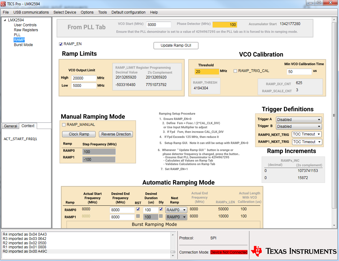
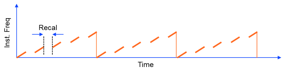
I am using the evaluation kit for this board, which includes the Reference Pro, to produce an ramp that is at least >1 GHz wide, but am only trying to do accomplish a 200 MHz sweep for now. From what I understand, this board accomplishes this by sweeping a certain bandwidth (say 20 MHz) before calibrating the VCO to a new frequency, then sweeping another 20 MHz, and repeating this until the full sweep is accomplished. The GUI allows for a minimum time to calibrate the VCO between these smaller sweeps, with the goal of achieving a consistent time between ramp functions. I have attached a files with register mappings which reference my current software state when using TICS Pro.

R112	0x700000
R111	0x6F0000
R110	0x6E0000
R109	0x6D0000
R108	0x6C0000
R107	0x6B0000
R106	0x6A0003
R105	0x699C40
R104	0x68FFFF
R103	0x673E00
R102	0x660000
R101	0x650000
R100	0x64C350
R99	0x63FD61
R98	0x62FFFD
R97	0x618800
R96	0x600028
R95	0x5F0000
R94	0x5E0000
R93	0x5D0000
R92	0x5C0000
R91	0x5B0000
R90	0x5A0000
R89	0x590000
R88	0x580000
R87	0x570000
R86	0x560000
R85	0x55CE00
R84	0x540001
R83	0x530000
R82	0x527800
R81	0x510000
R80	0x500000
R79	0x4F0040
R78	0x4E00BF
R77	0x4D0000
R76	0x4C000C
R75	0x4B0800
R74	0x4A0000
R73	0x49003F
R72	0x480001
R71	0x470081
R70	0x46C350
R69	0x450000
R68	0x4403E8
R67	0x430000
R66	0x4201F4
R65	0x410000
R64	0x401388
R63	0x3F0000
R62	0x3E0322
R61	0x3D00A8
R60	0x3C0000
R59	0x3B0001
R58	0x3A8001
R57	0x390020
R56	0x380000
R55	0x370000
R54	0x360000
R53	0x350000
R52	0x340820
R51	0x330080
R50	0x320000
R49	0x314180
R48	0x300300
R47	0x2F0300
R46	0x2E07FC
R45	0x2DC0DF
R44	0x2C3FA3
R43	0x2B0000
R42	0x2A0000
R41	0x290000
R40	0x280000
R39	0x27FFFF
R38	0x26FFFF
R37	0x250304
R36	0x240050
R35	0x230004
R34	0x220000
R33	0x211E21
R32	0x200393
R31	0x1F43EC
R30	0x1E318C
R29	0x1D318C
R28	0x1C0488
R27	0x1B0002
R26	0x1A0DB0
R25	0x190C2B
R24	0x18071A
R23	0x17007C
R22	0x160001
R21	0x150401
R20	0x14C848
R19	0x1327B7
R18	0x120064
R17	0x110110
R16	0x100080
R15	0x0F064F
R14	0x0E1E30
R13	0x0D4000
R12	0x0C5001
R11	0x0B0028
R10	0x0A10D8
R9	0x091604
R8	0x082000
R7	0x0740B2
R6	0x06C802
R5	0x0500C8
R4	0x040A43
R3	0x030642
R2	0x020500
R1	0x010808
R0	0x00A49C

In the attached configuration, I have the min calibration time at 25 microseconds, which should be enough. What I observe is that when the sweep is low, (say < 100 MHz), the ramp duration is fairly consistent. However, for sweeps larger than this (say > 200 MHz), I consistently see that the ramp duration varies randomly within +- 5% of the ramp duration. I would expect that the ramp duration, even if it does vary, would do so at much smaller deviation than this. I have observed this behavior even with longer minimum calibration times (64 microseconds). Any ideas? Thanks in advance.

  • Garret,

    For the automatic ramping feature, the frequency will ramp for a pre-defined frequency change given by the user and then the VCO will calibrate. However, if the pre-defined frequency change is too much , the VCO will automatically recalibrate. The amount the VCO frequency can change without the VCO needing to re-calibrate is defined as the calibration free range. We have no spec or guarantee for the calibration free range, but I am attaching a document that gives some measurements I have taken for this.

    If you want to ramp >200 MHz calibration free, you might find that the VCO might not always be able to do this, so it automatically calibrates. 200 MHz calibration free range is not realistic over process and temperature.

    The calibration is not always the same and there are multiple values of VCO_CAPCTRL that can give the same frequency, but they impact how far the VCO can go. If your ramp includes VCO calibrations that happen outside of when you define them to be, 5% variation is not unexpected.

    Regards,
    Dean
  • Dean,

    Thanks for the quick response here.

    My goal here is not to sweep >200 MHz calibration free. As you point out, this is not likely a viable solution on this board. I would like to sweep >200 MHz with consistent calibration times -- however long they may be.

    I am attempting to get the RAMP function to sweep 10 MHz, then calibrate in 25 microseconds, sweep another 10 MHz, then calibrate again for 25 microseconds, and then sweep again, etc. The board will do this, it is just that I cannot get the calibration time to be consistently 25 microseconds. Perhaps I need to give it a longer calibration time so that it is consistent, but I would hope the calibration time should not be too long.

    On another note, I intend to use this as part of a prototype FMCW radar system, is there an existing application note that uses this board for bandwidths > 200 MHz?

    Thanks again,

  • Garrett,

    This should be possible.  25 us should be long enough, but maybe it is a little marginal, depending on the OSCin frequency and phase detector frequency and CAL_CLK_DIV.  If the calibration takes longer than 25 us, then you will get irregular time period, so I think that you should try increasing it.  In reality, maybe to 30 us, but as a diagnostic, maybe to 50 us to just be absolutely sure that it is not a VCO calibration time issue.

    Regards,

    Dean

  • Dean,

    Again, thanks for the quick response :).

    In the register values I attached earlier, I could not get the VCO to calibrate at a consistent time even by giving it a minimum time of 64 micro-seconds, so I am wondering if there is another setting that I have failed to properly adjust. In what I attached, the phase-detector frequency was 100 MHz and the oscillator is just the on-board oscillator for the VCO, which is default 100 MHz, passed through a doubler.

    I believe there is also an oscillator I can use on the reference pro after adjusting resistor positions, but according to my reading of the data sheet(s), the jitter on the reference pro clock and the on-board clock of the LMX2594 is roughly the same, so I did not use that oscillator.

    Regards,
  •   Garrett,

    I tried to load the file, but it is only registers, but TICSPro has additional information in the GUI.  Even though you are not programming with TICSPro, it is an invaluable tool for register checking.

    When I loaded it in, I got a warning (you can mouse over colored boxes to get tooltip) that said FCAL_HPFD_ADJ should be adjusted and also that you cannot use the OSC_2X and R divider at the same time while ramping.  Maybe it is related to this.

    Regards,

    Dean

  • Thanks again for the help. I've resolved my issue based on this. I would have uploaded the .tics file as I am using TICS Pro, but it was not in the allowed file types when submitting a reply.

    I did notice the warning. I suppose I was expecting a "fatal error" as opposed to a "warning" when things would most definitely not work with a given set of parameters.

    I would just like to confirm, if possible, that this is roughly what the output should look like when operating in this mode:

    Note that this illustration highlights that nothing meaningful is output in during re-calibration and that the output frequency just before and just after a re-calibration should be roughly the same frequency.

  • Garrett,

    Great. I'm glad that we have resolution on this.

    Your plot looks like what one would expect.

    Regards,
    Dean