This thread has been locked.

If you have a related question, please click the "Ask a related question" button in the top right corner. The newly created question will be automatically linked to this question.

LMX2571: Calibration problem

Part Number: LMX2571

We are developing a DMR base station, using the LMX2571 on TX.

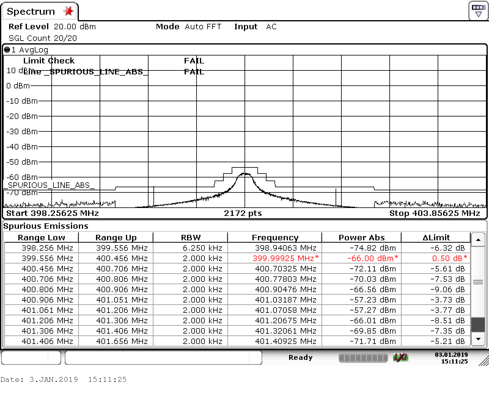
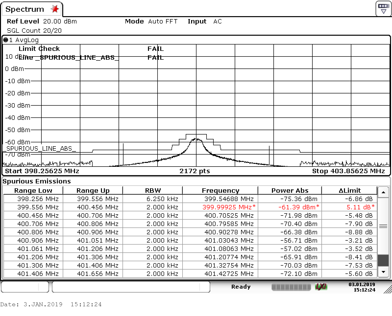
There are a number of frequencies at which the calibration of the PLL produces an unpredictable behavior. 

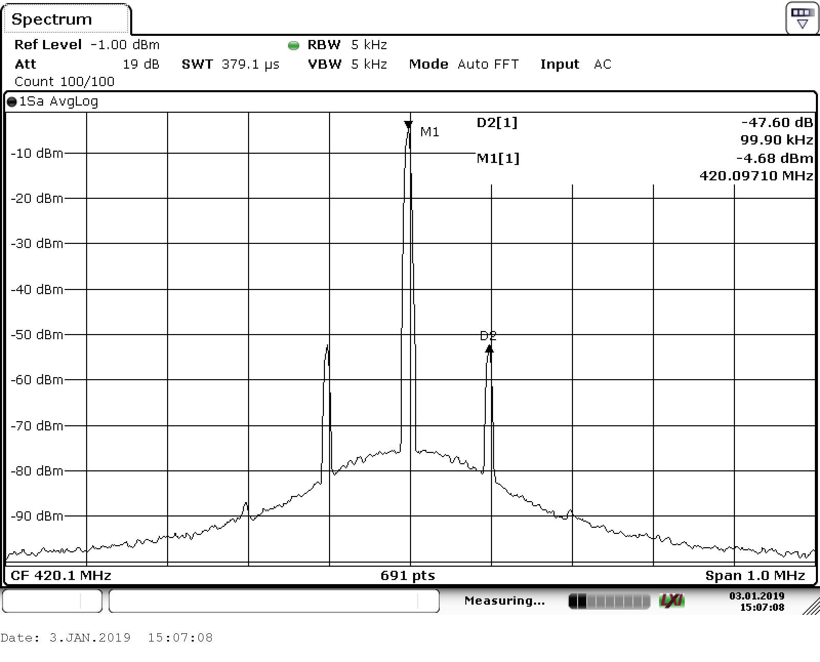
There are apparently two states into which the calibration can run. The following pictures show the facts: Each new calibration by writing FCAL_EN leads either to a Spurious with -47 dBc or one with -49 dBc with a change of 50:50. All other registers remain unchanged ! In our base station we found differences of more than 10 dB between the two calibration states.

What is the difference between these calibrations? Is it possible to determine which of the two states has been taken and how can be forced the better one ?

These screenshots were taken with LMX2571EVM at 421.1 MHz, programmed with TICs Pro and following registers:


R60    0x3CA000
R58    0x3A8C00
R53    0x357806
R47    0x2F6000
R46    0x2E001A
R42    0x2A0210
R41    0x290807
R40    0x28071C
R39    0x2711FB
R35    0x230C83
R34    0x221000
R33    0x210000
R32    0x200000
R31    0x1F0000
R30    0x1E0000
R29    0x1D0000
R28    0x1C0000
R27    0x1B0000
R26    0x1A0000
R25    0x190000
R24    0x18000E
R23    0x170E84
R22    0x168584
R21    0x150101
R20    0x14301B
R19    0x1303E8
R18    0x120000
R17    0x110000
R16    0x100000
R15    0x0F0000
R14    0x0E0000
R13    0x0D0000
R12    0x0C0000
R11    0x0B0000
R10    0x0A0000
R9    0x090000
R8    0x080004
R7    0x070E84
R6    0x068683
R5    0x050201
R4    0x043054
R3    0x030000
R2    0x021EB8
R1    0x010005
R0    0x000083

Here is an example from the base station at a reference frequency of 25 MHz, where the effect occurs more often.

  • Stefan,

    When the VCO calibrates, there can be more than one valid state.  For the calibration, the amplitude setting, the VCO core, and the VCO band within the core.

    The LMX2571 has 3 VCO cores.  5042 MHz is right near the boundary of two of the cores (VCOM and VCOH).   So it is no surprise that it could pick one or another with about 50:50 probability.  The spur could differ based on which core is chosen.

    Unfortunately, there is no way to read back the VCO core that the calibration chooses.

    That being said, there is a VCO_SEL bit (R46[1:0]) and VCO_SEL_STRT(R46[2]) that can set a starting preference for VCO that should be able to get the LMX2571 to favor one VCO core over another.

    I looked at TICSPro and didn't see these settings, so I will update it and this will be updated on the next time we release TICSPro from the web.  Until then, you can manually set VCO_SEL and VCO_SEL_STRT on the registers tab.

    Regards,

    Dean

    Regards,

    Dean

  • Hi Dean,

    thank you for the quick reply

    Unfortunately, the programming of register 46 does not lead to any other result or or remarkable effects

    The effect also occurs at frequencies that are not in the overlaping range of the VCOs, such as 401.05625 MHz resulting in fVCO = 4812.675 GHz

    In this example we get alternating results of -3 dB and + 3dB maximum spurios levels over the limits from ETSI EN 301 489-5.  This is not helpful for the certification.


                    f,                  fOsz, PreR, Mult, Post-R, Power,CP,  Spurios (dBc-85dB), SpurFreq

    found: [401056250, 25000000, 1, 3, 3, 4, 30] 2.89 -1056986.0
    using: [401056250, 25000000, 1, 3, 3, 4, 30] -3.01 -1056986.0
    found: [401056250, 25000000, 1, 3, 3, 4, 30] 2.93 -1056986.0
    using: [401056250, 25000000, 1, 3, 3, 4, 30] -3.08 -1056986.0
    found: [401056250, 25000000, 1, 3, 3, 4, 30] 2.87 -1056986.0
    using: [401056250, 25000000, 1, 3, 3, 4, 30] -2.91 -1056986.0
    found: [401056250, 25000000, 1, 3, 3, 4, 30] 2.93 -1056986.0
    found: [401056250, 25000000, 1, 3, 3, 4, 30] 2.92 -1056986.0
    found: [401056250, 25000000, 1, 3, 3, 4, 30] 2.92 -1056986.0
    found: [401056250, 25000000, 1, 3, 3, 4, 30] 2.93 -1056986.0
    using: [401056250, 25000000, 1, 3, 3, 4, 30] -3.01 -1056986.0
    using: [401056250, 25000000, 1, 3, 3, 4, 30] -3.04 -1056986.0
    using: [401056250, 25000000, 1, 3, 3, 4, 30] -2.95 -1056986.0
    using: [401056250, 25000000, 1, 3, 3, 4, 30] -2.87 -1056986.0
    using: [401056250, 25000000, 1, 3, 3, 4, 30] -2.90 -1056986.0
    found: [401056250, 25000000, 1, 3, 3, 4, 30] 2.91 -1056986.0
    found: [401056250, 25000000, 1, 3, 3, 4, 30] 2.91 -1056986.0
    found: [401056250, 25000000, 1, 3, 3, 4, 30] 2.95 -1056986.0

    Init seq:

    003ca000
    003a8c00
    00357806
    002f6000
    002a0202
    00290106
    0028061c
    002711fb
    00230fa0
    00220101
    00000c83
    00200000
    001f0000
    001e0000
    001d0000
    001c0000
    001b0000
    001a0000
    00190000
    00180000
    00170e84
    00168183
    00150101
    0014301f
    00130000
    00120000
    00110000
    00100000
    000f0000
    000e0000
    000d0000
    000c0000
    000b0000
    000a0000
    00090000
    00080548
    00070e87
    0006e583
    00050101
    0004201e
    00030000
    00020000
    00010000
    00000c83

    set freq to 401056250:

    0006e683
    00050301
    00042060
    00030000
    0002e560
    00010040
    00000c83

  • Sorry, the limits are from ETSI EN 300 113.
  • Stephan,

    Not only can the VCO core make a difference, but also the band withing the core can make a difference, but I would not expect it to be as much as the difference between cores. If the calibration causes this variation, then I don't think there are two many other things to do than design for worst case of the two cases.

    That being said, also try ways to mitigate the spur, such as using the programmable input multiplier (MULT) or changing the input format to the OSCin pin to be high slew rate, but low amplutude, like LVDS.

    Regards,
    Dean