This thread has been locked.

If you have a related question, please click the "Ask a related question" button in the top right corner. The newly created question will be automatically linked to this question.

LMX2594: Full Assist VCO Mode only locks sometimes

Part Number: LMX2594


Hi there,

I seem to ran into a dead end.

I've got a circuit with a LMX2594. I have frequency ramps running from 8 to 12GHz using no VCO Assist, Partial VCO Assist and also Close Frequency VCO Assist. In an effort of getting consistent lock times below 50µs I tried implementing Full VCO Assist.

I lock each frequency using no Assist VCO mode and read back VCO core, Cap code and DACI. Having send this data to a PC and convert it to 24Bit register values (1 R/W Bit + 7 Address Bits + 16 Data Bits) I can then stupidly send those Ramps from an external FPGA to my board.

This procedure has the benefit of having the VCO Cal data for analysation at hand. Plus the FPGA has a much higher SPI clock rate then software SPI on Atmel MCU.

Although this all works fine for Partial VCO Assist and also Close Frequency VCO Assist mode it doesn't seem to work with Full Assist VCO mode for me.

When I run my 256 step frequency ramp the output skips most frequencies and only locks at certain frequencies.

When I read back rb_LD_VTUNE (at Register 110) it is 2 (locked) for each visible frequency and 0 (unlocked/VTune low) for each frequency which is left out.

Those values I sent to the LMX are read back, that's what I'm confused about.

Can you help

PS:each frequency consists of:
R75 (CHDIV)
R45 (OUTA_MUX)
R44 (MASH)
R43 (NUM)
R39 (DEN)
R37 (PFD)
R36 (N)
R31 (CHDIV_DIV2)
R20 (VCO Core, VCO_SEL_FORCE)
R19 (Cap Code)
R16 (DACI)
R0 (FCAL_EN=0)

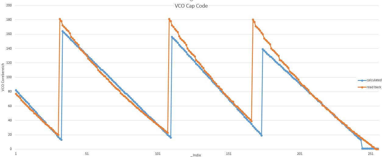
The following graphs compares values for Cap Code and DACI from the calculations using the formulas of the datasheet and the read back values. Strangly the output seem to lock each time the Cap Code is around 70 to 85.

  • Tobias,

    Thank you for providing this detailed explanation.

    1. You notice that the results from the no assist give different results than the calculated values from the datasheet. This is expected as these values vary for each individual device.
    2. Just to ensure this is clear that when you read back this calibration data, it is only valid for the individual device you read this back on.
    3. You mention that the VCO_CAPCTRL can change significantly and the PLL still lock. You say it works in a range of 70 to 85. Sounds about right. There is substantial overlap in the VCO bands to ensure that the VCO stays in lock even if the temperature drifts without reprogramming.


    Now let's look at the register writes:

    To read back, I would recommend:
    1. Set CAL_CLK_DIV=3 for maximum accuracy.
    2. Lock with No assist mode
    3. Read back, rb_VCO_SEL, rb_VCO_CAPCTRL, and rb_VCO_DACISET

    - From your results, it seems you are doing this correctly. I don't see the rb_VCO_SEL graph, but I assume you have it.

    To write I would suggest:

    Do this one time and it does NOT have to be done for each frequency change
    VCO_SEL_FORCE=1
    VCO_CAPCTRL_FORCE=1
    VCO_DACISET_FORCE=1

    Then to change frequencies, you write:
    VCO Calibration Information:
    VCO_DACISET
    VCO_SEL
    VCO_CAPCTRL

    R75 (CHDIV)
    R45 (OUTA_MUX)
    R44 (MASH)
    R43 (NUM)
    R39 (DEN)
    R37 (PFD)
    R36 (N)
    R31 (CHDIV_DIV2)


    So it seems like you could be doing the right thing, although I want to confirm that you are setting VCO_DACISET_FORCE=1 when you are writing your frequencies for full assist.

    Regards,
    Dean
  • Thank you very much for your quick and detailed response. After some digging your post helped me figure out the problem. DACISET_FORCE and CAPCTRL_FORCE weren't set to 1.
    Just for clarification:
    I tried programming the registers for each frequency in the order you suggested. I'm not sure if it is faster now. The limiting factor is SPI Clock speed (15MHz) because the FPGA isn't onboard.

    Concerning your second point.
    I'd be very happy if the read back values for the VCO calibration hold their validity for the duration of temperature drift as well as the lifetime of the device. That way I wouldn't need a calibration procedure after manufacturing.
    Concerning your third point.
    I think I expressed the problem a little poorly. I don't change VCO_CAPCTRL after lock. Each frequency has a single CAPCTRL value. But all frequencies which have CAPCTRL values outside of 70-85 simply wouldn't lock. Now I know why.

    Thank you again very much, after months of work the project now seems to reach a successful end.