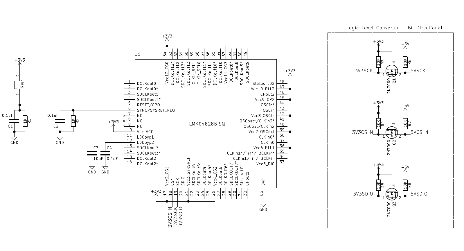
Hello, I had previously ask if the below circuit was correct for testing just the SPI communication of the chip ( https://e2e.ti.com/support/clock-and-timing/f/48/t/760667
What I have tried.
I found the following https://e2e.ti.com/support/clock-and-timing/f/48/p/649396/2386845?tisearch=e2e-sitesearch&keymatch=afe58jd18evm#2386845
power consumption on a powerdown instruction. I have verified that RESET(pin 5) is tied low
I found the following https://e2e.ti.com/support/clock-and-timing/f/48/t/505076?LMK04828-Not-listening-or-responding-to-SPI
Reset (pin 5) 0v
LDObyp1 (pin 11) ~2.5v
LDObyp2(pin 12) ~1.5v
OSCin (43) ~1.6v
CLKin0 (37) ~1.6v
status_LD1 (31) 0
status_LD2 (48) 0
CLKin_sel0 (58) 0
CLKin_sel1 (59) 0
the circuit above is drawing .355A at 3.3v , I have switched out IC's and have observed the same results.
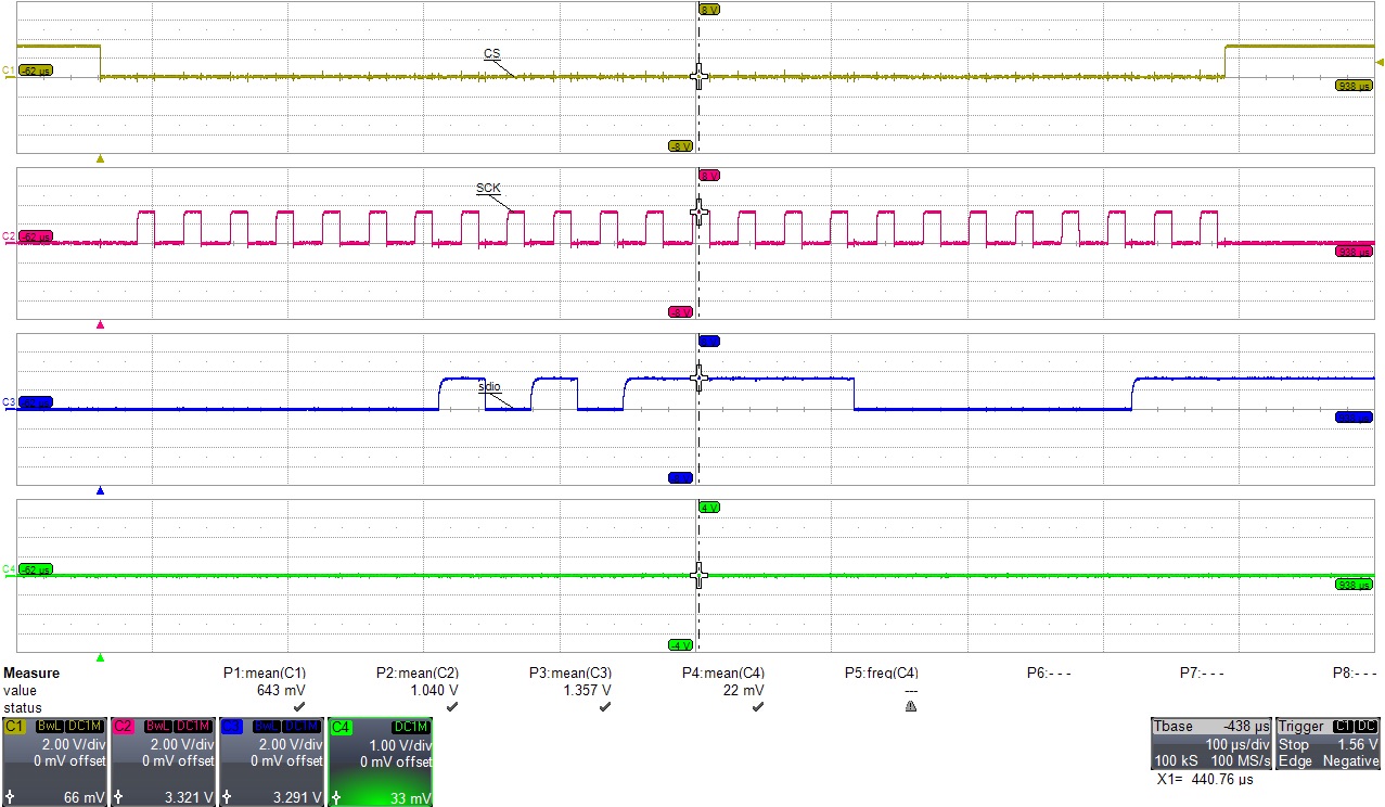
I tried a loop to change the status_LD1 by writing register 0x149 a value of 0x03 and then changing it to a value of 0x04. below is an example of the write. The values taken are measured at the chip