This thread has been locked.

If you have a related question, please click the "Ask a related question" button in the top right corner. The newly created question will be automatically linked to this question.

LMX2571: test problem

Part Number: LMX2571


Dear all:

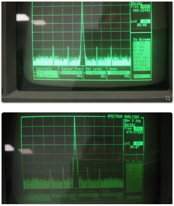
      When LMX2571 was tested, it was found that there were harmonics near LMX2571 frequency point, which led to low lead power. Currently, the frequency point of our interphone was 400~480MHz, and the frequency points of serious harmonics were 403.2mhz 500KHz, 422.4mhz 500KHz, 441.6mhz 500KHz, 460.8mhz 500KHz, 480MHz 500KHz.May I ask how to modify our software and hardware?

In addition, in our scheme of DMR, the modulation error of FSK is relatively large. Do you have any Suggestions for us in this aspect?

Thank you!

  • Hi Timsen,

    Could you provide your configuration with our GUI TICS Pro? Are you using internal or external VCO? What is your loop bandwidth?
    Assuming you are using 19.2MHz reference clock with the internal VCO, then the spurs that you saw are due to crosstalk between OSCin and VCO or fout. Crosstalk spurs is difficult to eliminate, the most effective way to avoid crosstalk spurs is use two OSCin frequencies. For example, you know that there will be crosstalk spurs at 479.975MHz with 19.2MHz OSCin. You may use, say 19.9MHz instead of 19.2MHz OSCin, then the spurs will go away.

    As for FSK error, could you tell us how did you implement FSK modulation?
  • Hi Noel:
    Now we are using internal VCO. If there is burr problem with internal VCO, is there any other way to reduce burr besides using two OSCin frequency avoidance methods? In order to meet the target requirements
  • Timsen,

    Two separate OSCin frequencies is the most effective way to reduce integer boundary spurs, but we also have the programmable input multiplier that can shift the phase detector frequency inside the chip as well.  It is not as effective, but still beneficial and does not require changing the OSCin frequency.

    Regards,

    Dean