This thread has been locked.

If you have a related question, please click the "Ask a related question" button in the top right corner. The newly created question will be automatically linked to this question.

LMK03328: Connecting digital inputs to 1.8V LVCMOS

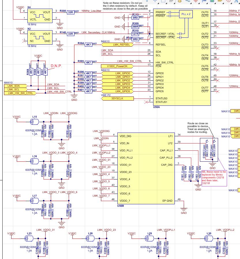
Part Number: LMK03328

Hello

I have connected the digital inputs of the LMK03328 to 1.8V LVCMOS logic as the minimum input voltage requirements are 1.2V/1.4V, however I am having trouble connecting to the board via I2C or toggling the SYNCN pin. Is it possible that the 1.8V logic is causing an issue? Thank you in advance.

Regards

  • I forgot to add that though the correct supplies are applied and power is stable, I am not seeing any clock outputs from the device either, and I would have expected default clock output after startup.
  • Hello Stuart,

    I need a little more information on how you have your device configured. Could I get a schematic and/or configuration file you are using to setup the device. Are you using the EVM or your own schematic?

    Also note that the chip itself requires an external clock source (even in the default setting).

    Thanks,
    Vibhu

  • Hello Vibhu

    Thank you for the feedback. The device does have its own clock source, it is being fed by a 16MHz clock in both primary and secondary inputs. I am using my own design, not the EVM. Please see the attached schematic outline, below. Note that V180C_PowerOk is also pulled up to 1.8V. In the firmware attached to the FPGA in question, after bootup, the LMK_GPIO0 line is driven high to deassert SYNCN. Any help you could provide would be greatly appreciate.

    Note that when I attempt to communicate on the I2C bus, the device provides a single, 10ms long, acknowledge after the address is sent but fails to acknowledge any register address writes after that.

    Thanks again.

  • Hello,

    Thanks for your schematic.

    You should not be able to see the output clocks until you have configured the PLL registers via I2C, so let's start from there.

    Looking at your schematic LMK_SDA and LMK_SCL are both connected through pull-ups to power net V180C. Can you confirm that even after the drop across the pull-up resistors they see at least 1.2 V?

    If you can also confirm this "V180C_PowerOk is also pulled up to 1.8V".

    Please send me some pictures of your I2C signals including V180C_PowerOk/PDN.

    Thanks,
    Vibhu
  • Hi Vibhu

    Thank you for your response.

    I can confirm that the I2C are indeed seeing at least 1.2V. This was the second place we looked (after ensuring that PDN was at least 1.8V). As a precaution, we built a mod onto the board to pull the pins up to 3.3V instead as we were concerned that the voltage levels on these lines were poor. You can see this in the figure below showing the SDA signal. The very long acknowledge at the end of the address write is clear. The slave address data being sent was 1010100, with the final 1 value to indicate a read - the complete data signal sent is 10101001, followed by the long ACK.

    Unfortunately, I do not have a capture ready of the SCL signal, but I observed it, and it looks similarly as good as the SDA signal.

    The PDN signal capture is provided below

    Considering these images, I find the problem very puzzling.

    Thank you again for your help.

    Regards,

    Stuart

  • Hi Vibhu

    I have some more images for you:

    This shows the SCL signal (green) and the SDA signal (yellow) together.

    Here is an image showing the ramp up of the 3.3V and the 1.8V signals:

    Do you have any other ideas for me?

    Regards,

    Stuart.

  • Hi again

    Will I be able to access the I2C using the clock setup as shown in the diagram above i.e. two 16MHz LVCMOS devices if the default EEPROM page 0 configuration is loaded at startup?

    Kind regards,
    Stuart Smith
  • Hello Stuart,

    I would encourage you to check your i2c protocol.

    To read a register value you need two commands:

    1) Write the register address, from where you want to read data:

    Slave address  + 0 + ACK + Register address + ACK

    2) Receive/read data from the register:

    Slave address + 1 + ACK + Received data byte + NACK

    From the screen shots you shared it looks like only the second step is shown.

    Please refer to section 3.1 & 3.2:

    http://www.ti.com/lit/an/slva704/slva704.pdf

    Thanks,

    Vibhu

  • Hi Vibhu

    Thank you for your feedback and assistance. I believe that you are correct. My Read/write bits were actually inverted. Many thanks again.

    Kind regards,

    Stuart Smith