This thread has been locked.

If you have a related question, please click the "Ask a related question" button in the top right corner. The newly created question will be automatically linked to this question.

LMX2491: why connect VCO to VCO/DIV with 18ohm resistor?

Part Number: LMX2491

Hello,

I have a customer working on a sensor and want to use this PLL for 24 GHz RF frequency.

Question:

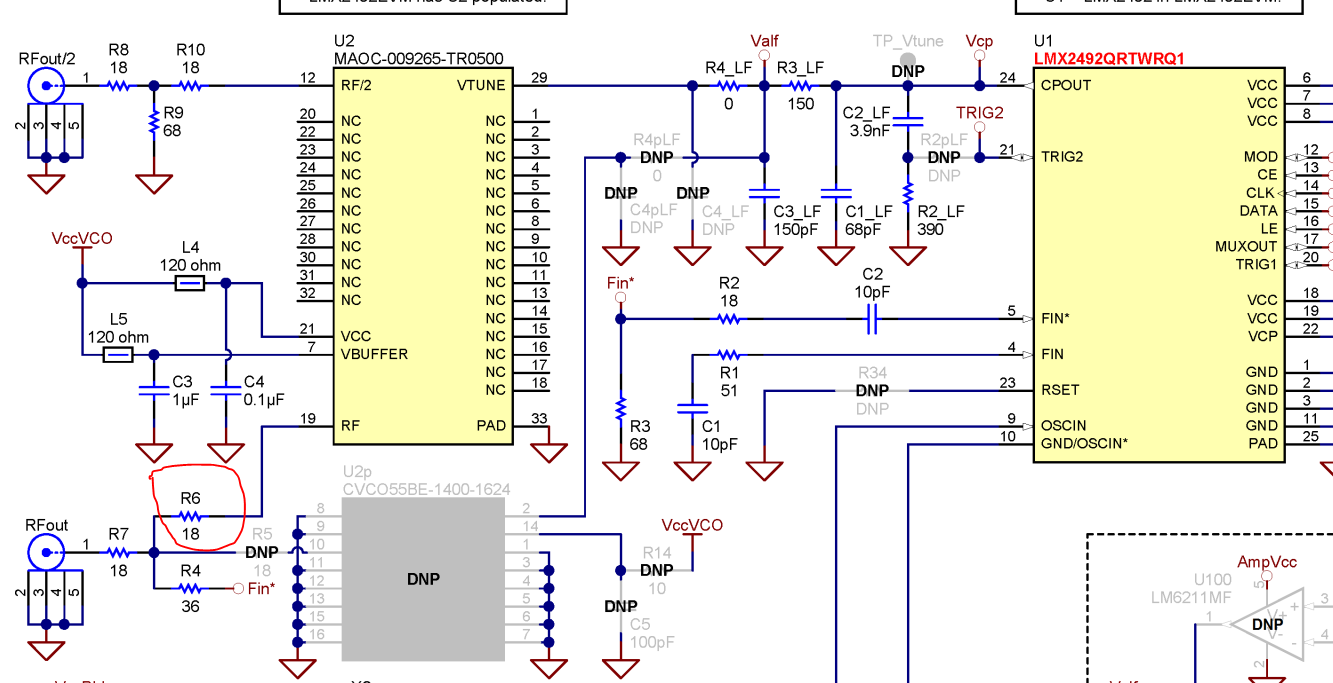
On the schematic, it is recommended that VCO is connected to VCO/DIV by an 18Ω resistor. Can you explain what purpose it serves? VCO/DIV pin will carry high frequency signal (1.5 GHz in my case) and CPout will output low frequency signal that controls VCO.

Thanks,

Kevin

  • Hi Kevin,

    The idea of the connection between pin 19 of U2 and pin 5 of U1 (I'm referring to the schematic in ) is two resister pads (shown below) in series.

    If RL is open, the equivalent impedance looking into V1 is 86, if RL is short, the equivalent impedance at V1 is 32. So this resister pad provides some matching no matter what load impedance is. Two of it cascaded narrows the range further to 47 ~ 59. The loss of one resister pad is 6dB when RL = 50Ohm. It may vary according to load impedance. 

    The reason this was done was that the input impedance of pin 5 of U1 is difficult to characterize and can vary with temperature. This method provides some robust, though not perfect matching. The prerequisite is that you have enough power to burn.

    Regards,

    Hao

  • Hi Hao,

    Thanks for the information! that is very helpful.

    LAST question....

    Can you please clarify where should I connect 18Ω resistor, to the 50Ω RF output of VCO (24 GHz) or to VTune input of VCO that connect to CPout? The diagram is unclear about that.

    Thanks,

    Kevin

  • Hi Kevin,

    I'm assuming you are talking about the 18Ohm here:

    So it should be connected to VCO output.

    Regards,

    Hao

  • The screenshot is from the user's guide that I attached in the previous post.

    Regards,
    Hao