This thread has been locked.

If you have a related question, please click the "Ask a related question" button in the top right corner. The newly created question will be automatically linked to this question.

LMK04832EVM: TICS Pro Bug?

Genius 12865 points
Part Number: LMK04832EVM

Hello Team,

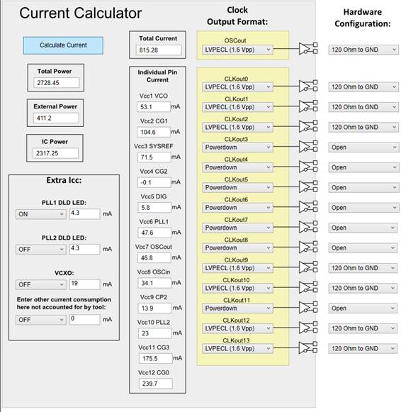
when checking the Current Calculator in TICS Pro we noticed that VCC4_CG2 is always set to -0.1mA independent of active or powered down clock outputs.
All other clock groups CG0, CG1, CG3) show a current of 104.6mA and additional 34.4mA per active output (LVPECL with 120Ohm to ground).

Can you confirm that CG2 can be calculated in the same way, please?

Thanks and Best Regards,

Hans

  • Hello Hans,

    Can you confirm which version of TICS Pro is used when you see this issue? In Help -> About TICS Pro, the version, build date, and part version information should be displayed. I am currently looking at version 1.6.9.0, build date 11-Dec-18, Part Version 2018-01-03, v1.0.0; this is the most up to date version available. I cannot reproduce the behavior described in your post using the TICS Pro currently available on the web, and CG2 computes correctly for me. If your version of TICS Pro is older, I recommend downloading the updated version and checking again.

    Regards,
  • Hello Derek,

    the latest version has been used. See screenshot below. What else could be the reason for this, please?

    Can you confirm that the CG2 current is calculated the same way as the other groups?

    Thanks and Best Regards,

    Hans-Günter

  • Hans,

    I determined that the behavior can be reproduced if CLKout4_5_PD = 1 and CLKout6_7_PD = 1. I think the current calculator "clock output format" selectors do not reflect the actual channel powerdown behavior. I will look into this further, as I think that setting the "clock output format" selectors to "powerdown" should override the channel settings in the current calculator. Also, I think the value at powerdown may need to be recharacterized, since it is unlikely that the device sources current out of the VCC pin when the channels are powered down.

    Regards,
  • Update:

    I observed that if PLL2_PD or PLL2_PRE_PD are toggled, the current is 0mA instead of -0.1mA. I think that we measured our base case and subtracted it as each block was powered on or off. So there were probably thermal fluctuations in the earlier base case that changed the base current by a small amount. This is an estimate of the current consumption, and it remains very close to typical values, so recharacterization is not necessary.

    As for the clock output format controls, the clock output path will still draw current even if the output format buffers are powered down. This is not a mistake, it just may not be intuitive if the user is unaware that the register settings in the rest of the TICS Pro pages will affect the current calculator estimate. We can keep this in mind if an update is required in the future.

    Regards,