This thread has been locked.

If you have a related question, please click the "Ask a related question" button in the top right corner. The newly created question will be automatically linked to this question.

LMK03328: How to power up LMK03328 with register default value, EEPROM page 1, or EEPROM page 4

Guru 19785 points
Part Number: LMK03328


Hi Team,

Q1). Please allow me to clarify the pin settings how to power up the device with the register default value.
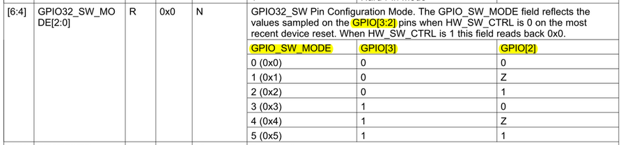
My understanding is to leave GPIO3 and GPIO2 pins Floating (open), am I correct ?

GPIO3 = Floating
GPIO2 = Floating

Q2). My another question is that following table is described in the EVM user's guide.
EEPROM page1, page4, and register default setting says the same "MID" for GPIO pin state.
However, my understanding is the following setting.
Am I understanding correctly ? 

Best Regards,

Kawai

  • Hi Team,

    Q3). Isn't GPIO[3:2] pins 4-state pin instead of 3-state pin ?

    I see following description in the LMK03328 datasheet, page 32.
    There is discrepancy between a) and b).

    a). GPIO[3:2] are purposed as 3-state pins (tied to VDD_DIG, GND, or VIM)
    b). When GPIO[3:2] are left floating, EEPROM is not used and the hardware register default settings are loaded.

    It would be very much helpful if the corrected table 3 in my previous post is shown in this page.

    Best Regards,

    Kawai

  • 1) Yes

    2) I took a lab measurement and the GPIO2 and GPIO3 pins read ~0.9V when left floating. In the table above MID = floating = VIM (~0.9 V) regardless of whether you are trying to access page 1, page 4 or Register Default Mode.

    3) These pins are 3-state pins, high, mid (~0.9V/floating) and low. When GPIO[3:2] are left floating setting mid, mid is selected corresponding to register default mode.

  • Hi Vibhu-san,

    I really appreciate for your great support.
    I have one additional question to your comment on 2) and 3).

    Did you measure the pin voltage using the EVM ?
    If this is the case, this is because the EVM has external resister divider.

    Can we understand as the GPIO2/GPIO3 pins internally have pull-up and pull-down to apply (biased to) 0.9V.
    We would like to make sure which is the TI recommendation, to leave the pin floating or to bias externally to VIM=0.9V.

    If we can leave these pins floating to set to the MID voltage internally, it is very much helpful if you could modify the datasheet to standardize the GPIO[3:2] table description  to "F (Floating)" instead of "VIM" or "Z", because, they are confusing us. It would also be a merit for customers to get rid of two external components to save space for each pins.

    Thanks in advance.

    Best Regards,
    Kawai

    [LMK03328EVM Schematic]

  • Hi Vibhu-san,

    I tested with my EVM removing the above R106 and R107 on GPIO2 pin and measured the pin voltage with JP21 jumper OFF.
    I couldn't see 0.9V at GPIO2 pin, it was around 0V.

    From this result, I believe GPIO[3:1] are 4-level input pin or 3-level pin which must have H, L or VIM(0.9V) applied.

    Could you please confirm with the device designer, whether these pins really can be left open ?

    Best Regards,
    Kawai

  • Hi Kawai,

    Sorry for the confusion. You must use external biasing on GPIO[3:2]. I notice this was answered in another post: e2e.ti.com/.../795641

    I will check with the design team for confirmation. I should get a response within a few days.

    Kind regards,
    Lane
  • Hi Lane-san,

    Yes, that was my understanding when booting from EEPROM page1 or page4 setting.

    What confuses me is that every table have different description and are not standardized.

    Please clarify the following three items.

    - If it is correct to leave GPIO [3:2] pins floating to use register default.

    - If it is correct to apply VIM=0.9V to GPIO[2] pin to use EEPROM page1 or page4.

    - If GPIO[3:1] pin is 4-level pin or 3-level pin.

    Best Regards,
    Kawai

    [Datasheet describes to float GPIO[3:2] pin to use register default setting]

    [Datasheet page 59, GPIO[3:2] is described to set to VIM]

    [Datasheet page 85, R8 table shows "Z" for EEPROM page1 and page4 GPIO[2] pin setting, no register default setting shown]

    [User's Guide page 13, Table 3 shows "MID for EEPROM page1, page4 and register default]

  • Hi Lane-san,

    Could you please please simply fill in the "?"  in the below table with whether "Floating" or "VIM (0.9V)" ?

    It would be helpful if we could have the information asap, since customer needs to fix their schematic within this week.

      GPIO3     GPIO2     Device Mode / Page Select
       Low    Low   Soft Pin Mode, EEPROM Page 0
       Low       ?   Soft Pin Mode, EEPROM Page 1
       Low    High   Soft Pin Mode, EEPROM Page 2  
       High    Low   Soft Pin Mode, EEPROM Page 3
       High       ?   Soft Pin Mode, EEPROM Page 4  
       High    High   Soft Pin Mode, EEPROM Page 5
         ?       ?   Register Default Mode

    Best Regards,
    Kawai

  • I believe all the "?" should be "VIM (0.9V)".

    I configured the EVM to GPIO2 and GPIO3 floating, this implies 0.9V on the EVM because of the pull-up, pull-down resistor bias you pointed out. I then did a read-back onto TICSPro to see the settings listed for Register Default Mode.
  • Hi Vibhu-san,

    Thanks for your comment.

    Regarding the datasheet description, many customer may be using GPIO2 and GPIO3 as floating (Hi-Z) on their board, over writing the registers which may be needed to be changed from the register default value. This might be the root cause that some customer is seeing unexpected behavior.

    There are several description to "float" the GPIO2 and GPIO3 pin for the device to start up with the register default value.

    Please make modification to this typo asap and it would be much better to describe each setting in the table such like above so that it is easy to understand. 

    Best Regards,

    Kawai

  • Kawai-san,

    Thank you for your input!
  • GPIO [3:2] Summary

      GPIO3     GPIO2     Register Information (Soft Pin Mode)
       Low    Low   EEPROM Page 0
       Low    VIM*
      EEPROM Page 1
       Low    High   EEPROM Page 2  
       High    Low   EEPROM Page 3
       High    VIM*
      EEPROM Page 4  
       High    High   EEPROM Page 5
       VIM*
       VIM*
      Register Default

    * VIM = 0.9V(TYP)