This thread has been locked.

If you have a related question, please click the "Ask a related question" button in the top right corner. The newly created question will be automatically linked to this question.

LMC555: astable vibrator alternative

Part Number: LMC555
Other Parts Discussed in Thread: SN74LVC1GX04

Hello,

Initially, I was looking to use the LMC555 as an astable vibrator with PNP transitor + integrating capacitor to generate a high frequency (1Mhz) ramp or sawtooth signal, for the purpose of feeding it into a comparator to generate an "analog" PWM with high duty cycle resolution and precise (+consistent) period.

The appealing features of the LMC555 were its high frequency of operation, extremely low power consumption, and self-oscillating capability. However, as I need to tune the frequency precisely to 1 Mhz, the propagation delays and rise/fall times make this unsuitable for my application (I also read in another forum that this would not be appropriate for generating e.g. 2MHz square wave with high precision). As I am not looking to create a 50% duty cycle (rather, a low-power, high resolution ramp/sawtooth signal), I do not think a crystal oscillator would be suitable for my application. Does TI offer any alternatives that I can investigate for my application?

Thanks.

  • Hello Saima,

    For the precise 1MHz and PWM control, I suggest a crystal oscillator where you can tap the analog portion of the oscillator. TI has SN74LVC1GX04 Crystal Oscillator Driver (with 1MHz crystal) where you can use X2 pin that I expect is a 1 MHz sine wave. That can go to a comparator to get high resolution PWM. The PWM will not be precise on it's own because the amplitude and DC offset of the sine is not a constant. I'll ask logic apps if they have a sample waveform for this X2 pin waveform. 

    The fast responding option to make precise duty cycle is to extract the sine wave's DC offset and amplitude and apply that to automatically compensate for drift in sine wave voltage. 

    The slower response option is easier to implement. See this blog concept where an op amp compares the PWM output duty cycle (average DC voltage) to the input PWM control signal and the op amp error output sets the PWM controller voltage. In your case, the error amp output goes to the comparator.

  • Hey Saima & Ron,

    I don't have any waveforms for the LVC1GX04 on hand, but there is an app note for similar devices like the LVC1GU04 that shows waveforms here: Use of the CMOS Unbuffered Inverter in Oscillator Circuits

    Typically, the signal at the inverter's output is a rounded off square wave or sine wave -- I've seen both. If you build the oscillator with an op amp, you should be able to tweak the feedback path gain to get the wave shape you need.

    You can also do this to an extent with an unbuffered CMOS inverter (like the crystal driver in the LVC1GX04 or the LVC1GU04), but you have much less gain to work with - an added series input resistor and feedback resistor work together exactly like an inverting op amp circuit, just with much lower open-loop gain.

  • Saima,

    So it looks like there will be a lot of clipping at X2 pin, however that can be made linear again with a simple RC low pass filter set to 1 MHz or better yet a fraction of 1 MHz. The lower the cutoff frequency, the more triangle like the waveform becomes; note that the peak to peak voltage also decreases with lower cutoff frequency. With the LPF filter you could use the main square wave output instead of the X2 pin. So that is my new suggestion.

    Perhaps no peak detector, no average, no error amp servo is needed if 1 MHz was fixed duty cycle, ideally 50%. Supply would set 'triangle' wave amplitude and offset provided that R and C for low pass filter are accurate. A toggling flip flop would be 50% DC 1 MHz output if 2 MHz was its input clock.

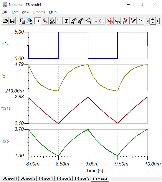
    Here is result for a square wave input (F1-) and LPF output with cutoff set to 1 MHz (fc) and fc/3 and fc/10. Note fc/3 is a nice compromise for amplitude and wave shape.

    Ok this was 1kHz , but it works the same at 1MHz 

  • Great, thanks! I will look into this. I can construct a ramp / sawtooth using 2 triangle waveforms delayed half a period. I also like the closed-loop error implementation, but will have to see if the response time will be suitable for my application.

    This is excellent reading material for me to go through.

    Best,

    Saima

  • Saima,

    Construct and delay half periods? None of that will be needed unless you must preserve the phase of the 1 MHz output. Meaning that that timing edge of the 1MHz source signal must coincide with the edge of the PWM output signal.

    If the phase of the output 1 MHz PWM doesn't matter, then that fc/3 signal can go to one input of the comparator and the control signal can go the the other input. As the control signal goes from 1.3V to 3.7V the comparator output will have a duty cycle that varies from 0% to 100% with an expected linearity error less than 1%.

  • Hi Ron,

    >>Meaning that that timing edge of the 1MHz source signal must coincide with the edge of the PWM output signal

    Yes, preferably this would be the case, as I could use the source signal to clock the synchronization of the system in later stages. Thanks!