This thread has been locked.

If you have a related question, please click the "Ask a related question" button in the top right corner. The newly created question will be automatically linked to this question.

CDCE62002EVM: CDCE62002EVM: The PLL is lock on the GUI software but the Eval board PLL is not locked

Part Number: CDCE62002EVM
Other Parts Discussed in Thread: CDCE62002

Hi There,

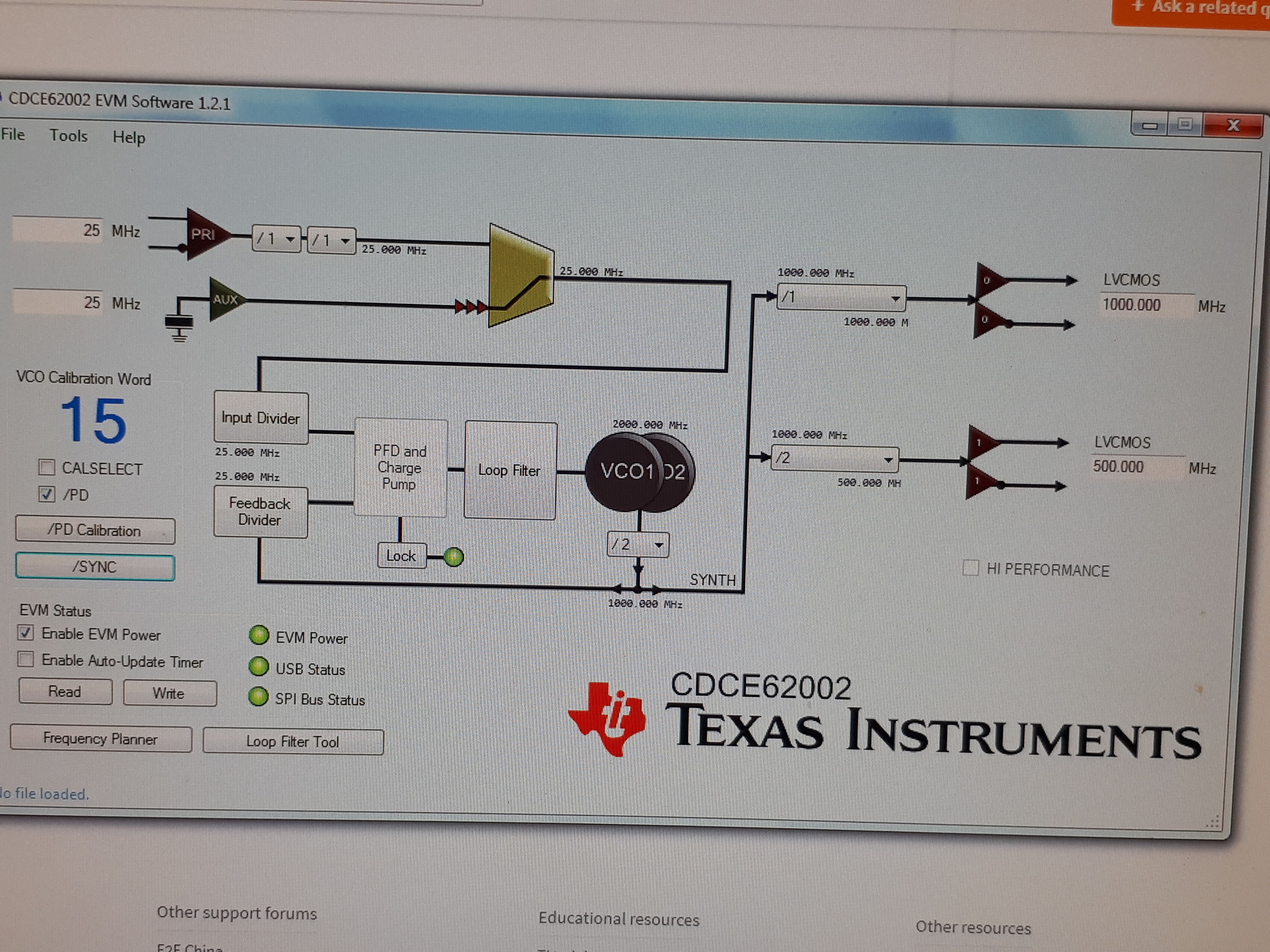
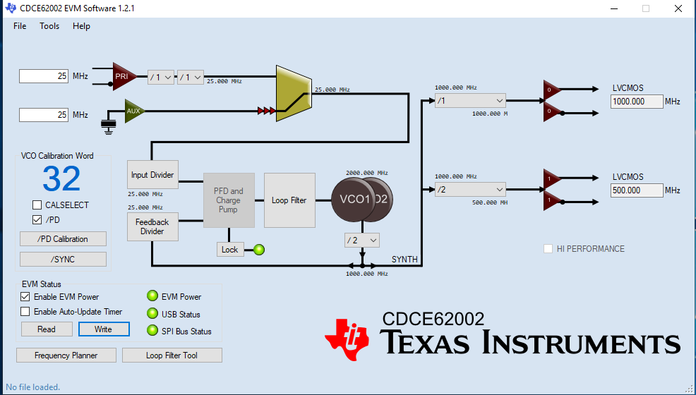
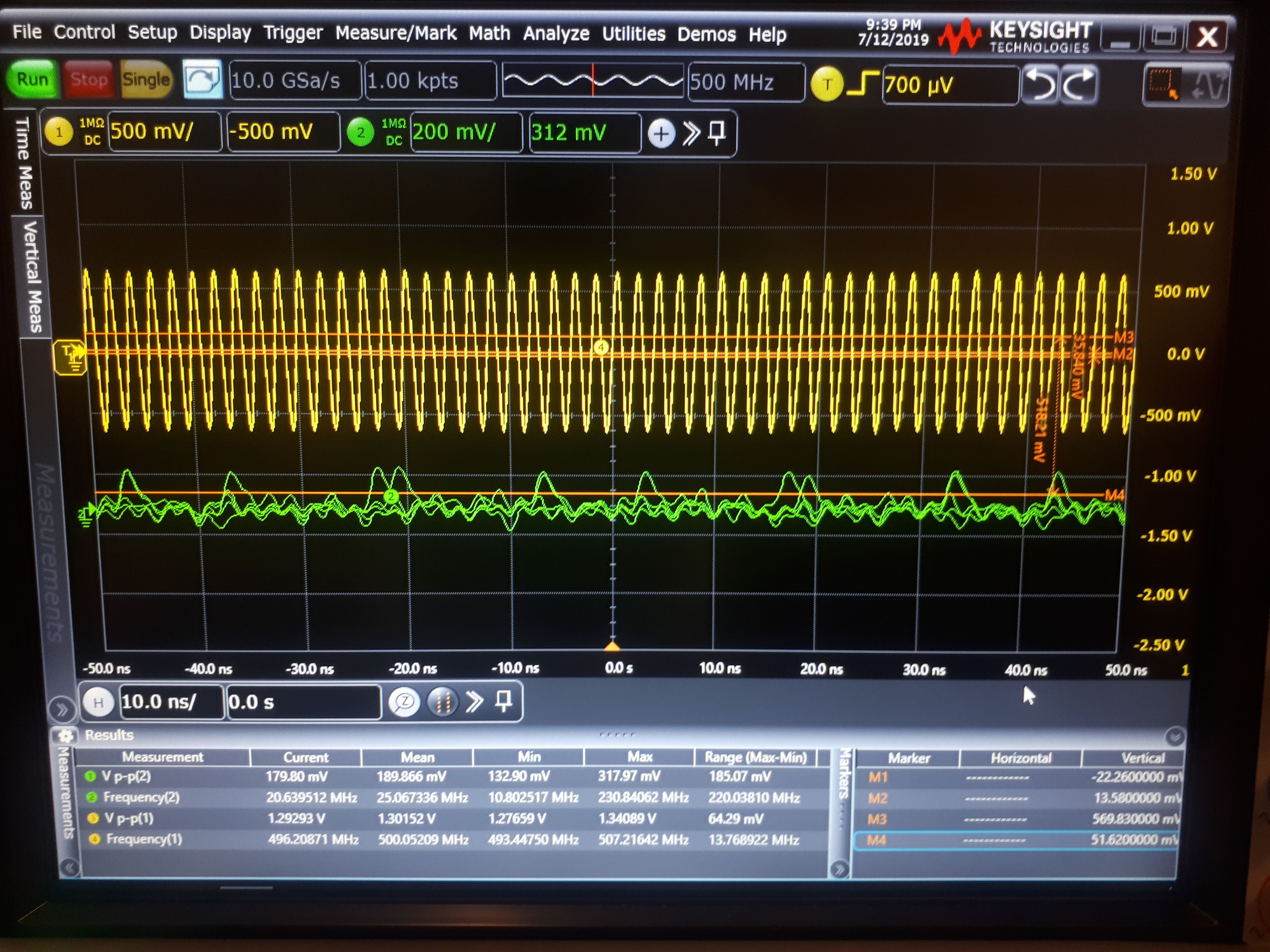
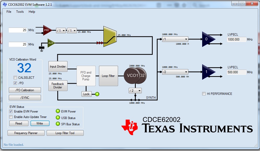
I have bought CDCE62002EVM recently and am trying to generate 1000MHz and 500MHz. I have used the Frequency Planner to setup the CDCE62002 GUI initially to generate these frequencies at the output ports. Even though I have been able to lock the PLL on the GUI software, I could not make the Eval board PLL locked, and the LED D33 on the Eval board is off.

CDCE62002 GUI Screenshot:

Eval board image:

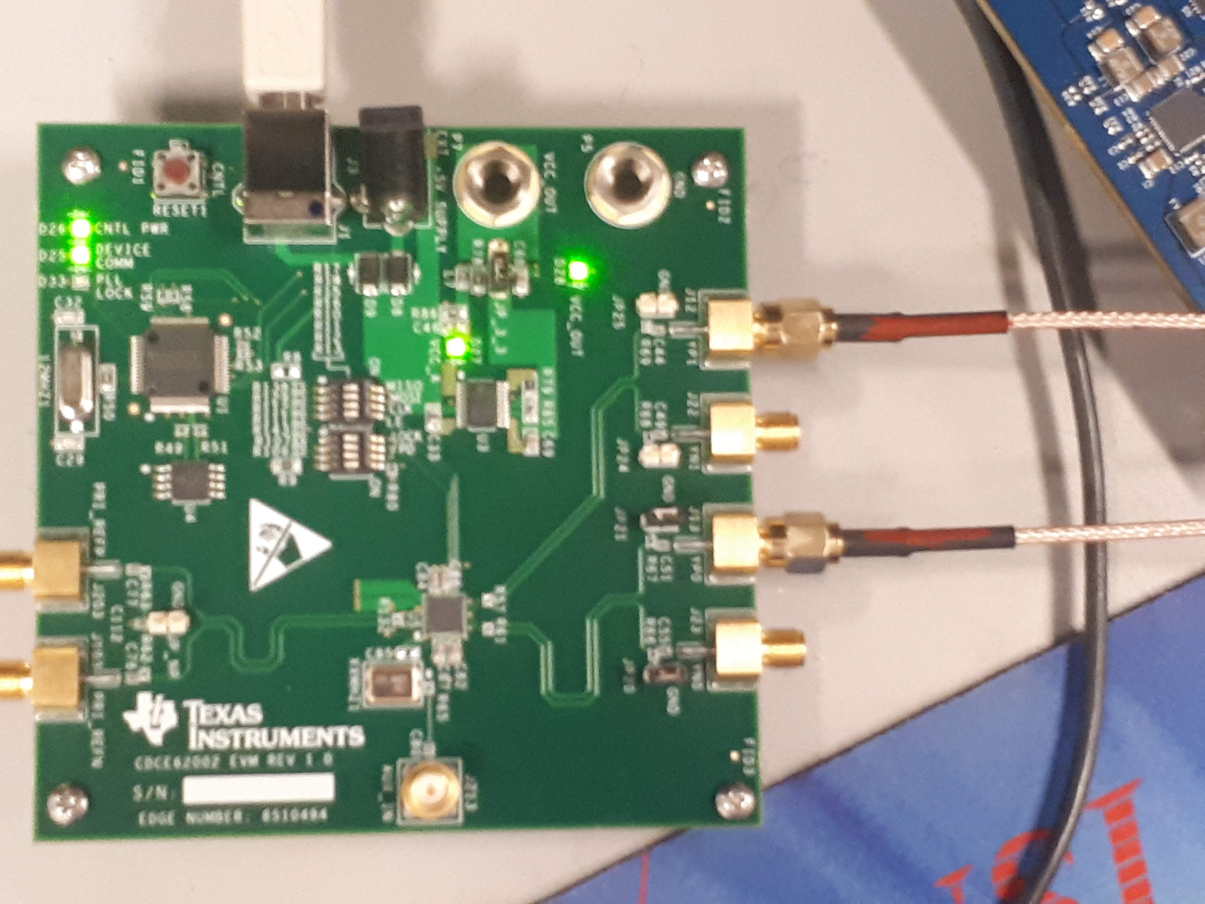
Could you please let me know how I can work around the issue and lock the Eval board’s PLL?

Thanks,

Ed

  • Hi Ed,

    I'll try it on the bench and get back to you soon.

    Regards,

    Hao

  • Hi Ed,

    I'm not very familiar with this device (the people who supported this are no longer with our team), but I got it to lock with default configurations by changing the input to crystal input as you did in the GUI, checking the PD box, and clicking "sync" as well as "calibration". I also changed the output format to LVCMOS and removed jumper JP21 for output 0.

    I did similar things and got the 1000MHz/500MHz to lock.

    Regards,

    Hao

  • Hi Hao,

    As you suggested, I removed the JP21 Jumper, clicked "Sync" and "Calibration", changed the output format to LVCMOS, and write all registers. The board cannot lock even though the GUI green lock light is on.  I rest the board and go through the same process, but no luck.

    CDCE62002 GUI Screenshot:

    Eval board:

    I am wondering if upgrading the firmware can help. I appreciate for any advice on how to work around the locking issue.

    Best,

    Ed

  • Hi Ed,

    What does your output look like? Is there no output at all or there is output but its frequency is not accurate? Could you attach a snapshot of your output?

    Regards,

    Hao

  • Hi Hao,

    The J12 port output signal is 500 MHz Sin wave with the 1.5Vp-p, but the J13 port output signal is a random one with the 40mVp-p. Please see the blow screenshot.

    Please kindly advise.

    Thanks,

    Ed

  • Hi Hao,

    Any updates?

    Ed

  • Hi Ed,

    Sorry for the delay, I was out of office. I'm attaching the screenshot of GUI and exported register: 

    https://e2e.ti.com/cfs-file/__key/communityserver-discussions-components-files/48/CDCE62002_5F00_2019_5F00_07_5F00_08.ini

    I used default loop filter setting and turned off all 4 pins of SW9 and SW10 at the back of the board. Please try different output formats, with/without the jumper and so on.

    Regards,

    Hao

  • Hi Hao,

    I loaded your .ini file (File/open), turned off all four pins of SW9 and SW10 on the back of the Eval board, and write to all registers by clicking the Write button. The software GUI indicates the PFD and Gharge Pump is locked ( the GUI Lock LED is on), but the Eval board is not locked yet and the D33 Led is still off.

    For LVCMOS, The output for J12 and J22 is shows 1.4Vp-p 500MHz, but the J13 and J23 shows noise regardless jumpers are on or not.

    For LVDS and LVPECL, The output for J12 and J22 is shows 400 mVp-p 500MHz, but the J13 and J23 shows noise regardless jumpers are on or not.

    I appreciate for any advice on how to lock the Eval board.

    Thanks,

    Ed

  • Hi Hao,

    Any updates?

    Ed

  • Hi Ed,

    I didn't light the D33 on the board either. I looked through the schematic but couldn't turn it on. However, looking at the scope and spectrum analyzer I see a stable tone without frequency drifting and I can tell that it's locked.

    For the 500MHz output that is working, can you change the output divider to 1 and see if you get anything? Same for the 1000MHz output, change the output divider to 2 and see if you get an output of 500MHz.

    Regards,

    Hao

  • Hi Hao,

    I set J22 output port to 500MHz , and J23 to 1,000 MHz, the J22 output signal is 500 MHz, but the J23 output signal is noise again:

    where the outputs are

    To test if the eval board  for the lower frequency than 1,000 MHz, . I set J22 output port to 500MHz , and J23 to 333.33 MHz, the J22 output signal is 500 MHz, and the J23 output signal is 333.33 MHz:

    where the outputs are

    Yes, the Eval board can locked its outputs at the lower frequencies  (i.e. the 500 MHz and 333.33MHz signals) even though the D33 lock LED is not on.

    It looks like that the CDCE62002EVM, which is in my hand, is not capable of locking at the 1,000 MHz frequency. Could it be a manufacturing defect? Please kindly advise.

    Thanks,

    Ed

  • Hi Ed,

    The 500MHz vs 1000MHz output frequency should not affect lock status, because when we say that the device PLL is locked, it means that the VCO output is locked to the input. The only difference between 500MHz and 1000MHz is that the output divider value is different. In both scenarios, the PLL itself is locked.

    I know it's less likely, but could it be because of the limitation of your scope? Did you set any sort of filtering? Can you try verifying the output using a spectrum analyzer instead?

    Regards,
    Hao

  • Hi Hao,

    The Eval board cannot lock on 1,000 MHz.

    I set the channel 1 divider to “2” and the channel 2 divider to “1” so that the J22 output signal and the J23 output signal frequencies are at 500 MHz and 1000 MHz, respectively. After rewriting all the registers, the J22 output signal is at 500 MHz, but the J23 output signal is noise:

    where the outputs are

    For validating the Eval board performance at the lower frequency, I set the channel 2 divider to “3” (instead of “1” or “2”) so that the Eval board can generate a signal at the 333.33 MHz frequency at the J23 output port. After rewriting all registers, the J23 output signal successfully generate the 333.33 MHz signal:

    where the outputs are

    As you can see, The CDCE62002EVM board, which is in my possession, can generate and lock at any frequency other than 1000MHz while your board can lock at 1000MHz, as well. I am wondering if we can conclude that my Eval board has a manufacturing defect and if we can exchange it. Please kindly advise asap.

    Thanks,

    Ed


  • Hi Ed,

    To exchange Eval board, please get help at TI store: https://www.ti.com/store/ti/en/

    However, I can't think of any reason why there's no output at 1000MHz. As I said, the 500MHz and 1000MHz share the same VCO core, so when one is locked, the other is also locked, so the problem is not with the PLL but with the output itself. Can you try some other frequencies between 500MHz and 1000MHz using the frequency planner?

    Regards,
    Hao

  • Hi Hao,

    I have tried to generate other frequencies between 501 and 999MHz, and had no luck initially. I opened your .ini file and clicked on Calibration and Sync buttons, and writing all registers. I still would see noisy output at 1000 MHz port until I switched the scope input impedance to 50 ohm and suddenly, bingo (the scope shows 1000 MHz signal)!

    Therefore, generating signals at the 500 MHz and below is not sensitive to load mismatch (both 1MOhm and 50 Ohm); however, generating signals between 500MHz and 1000MHz is sensitive to mismatch impedance and can only works with 50 Ohm.

    Thanks,

    Ed