This thread has been locked.

If you have a related question, please click the "Ask a related question" button in the top right corner. The newly created question will be automatically linked to this question.

CDCI6214: about run with EEPROM of CDCI6214

Part Number: CDCI6214
Other Parts Discussed in Thread: USB2ANY

Hi dear supporting team,

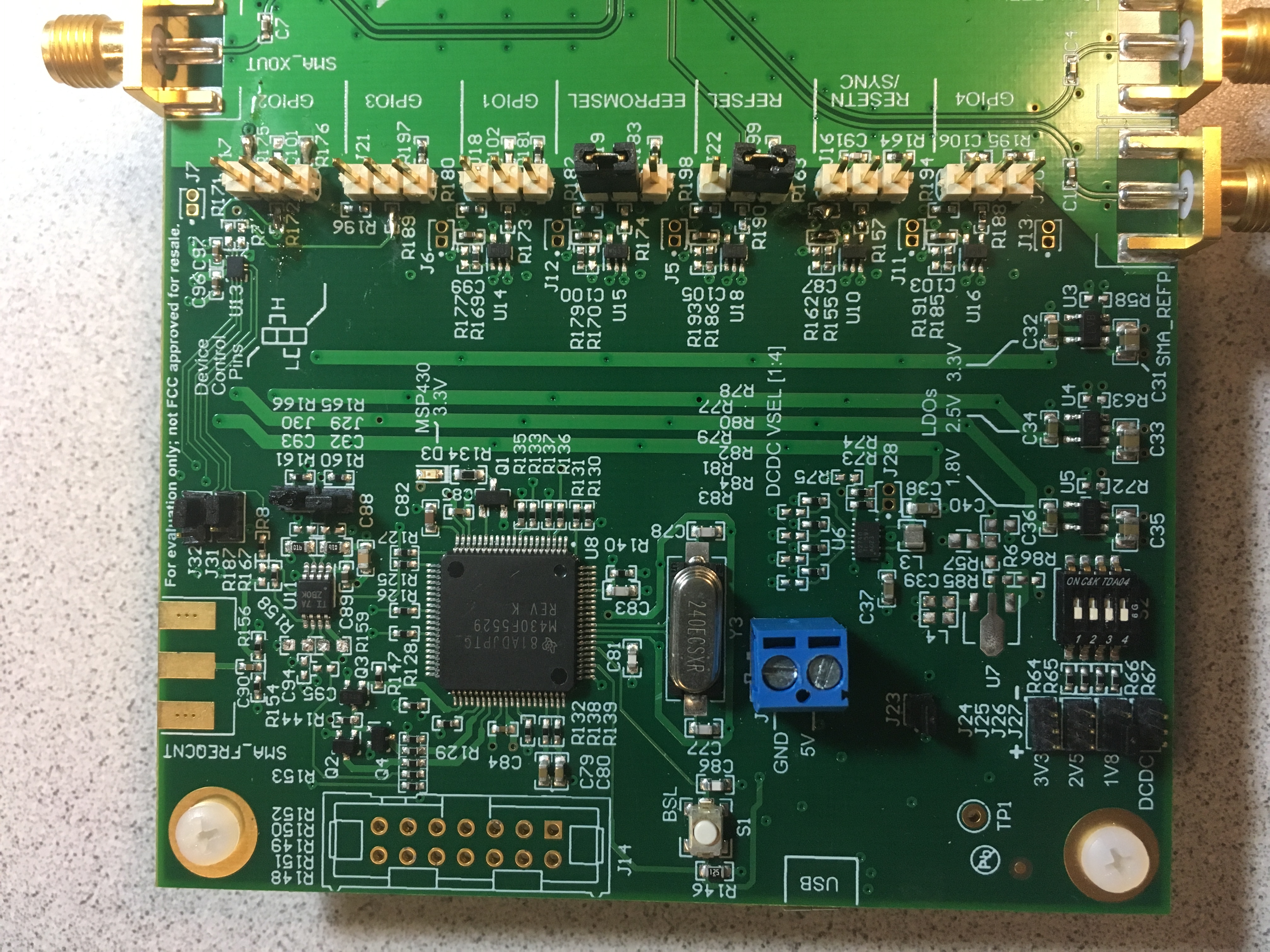
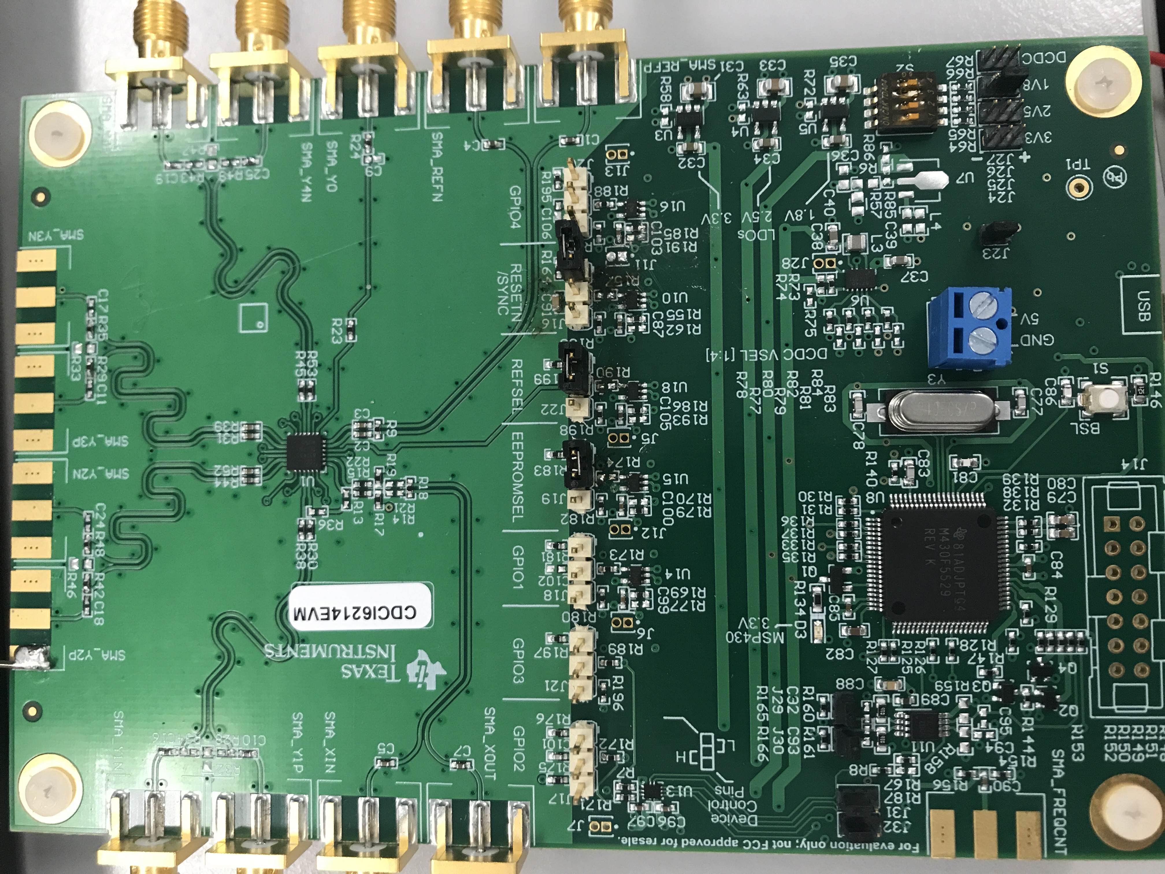
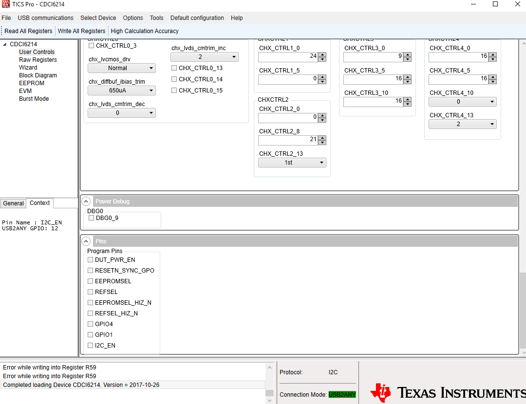
for CDCI6214 EVM, I found even with a EEPROM page0 burned , it still need open the GUI (TICS pro)  to make it run from EEPROM, (I have set REFSEL and EEPROMSEL to both Low),  and after probe, I found when GUI open, it will send a low level pulse to RESET pin. 

so is there anyway to omit the requirement of sending low level in reset pin? tks a lot!

  • Hello Vera,

    The EVM has been defaulted to work with TICS Pro. Hence, the control lines are controlled through TICS Pro SW.

    For making the board independent, 

    remove R157, R174 and R190. This will disconnect EEPROMSEL, REFSEL and RESETN from TICS Pro control (Page 23 of EVM Guide).

    Connect jumpers J16(2-3), J19(1-2) and J22(1-2) - EEPROMSEL=L, REFSEL=L and RESETN=H.

    Power cycle the board.

    We'll need to verify the changes if this would work. Please allow us some time to verify it.

    Regards,

    dinesh.

  • https://e2e.ti.com/cfs-file/__key/communityserver-discussions-components-files/48/OPTIMIZED-SETTING-of-6214-FOR-GOTA-LVPECL.7zHi Dinesh,

    thank you for reply! I verify the method in the lab, it does not work.  and I have changed the power supply to let MCU directly supply 1.8V to CDCI6214. but still no output. (I have burned verified regs into the chip). seems still need the low pulse at RESET PIN to send signal out. do you have any suggestion?

    and BTW, I have below application which request as good phase noise as possible: input 25M ref, output 26M & 52M, I found by tuning the input cap of the crystal will help decrease 1kHz offset phase noise, the best setting I got is as attached, could you pls help verify very it could be improved or not? tks a lot!

  • Hi Vera,

    The reason why Ticspro is still needed is that the GPIOs are controlled by the microcontroller. To disengage with the microcontroller, please remove resistor R174, R190 and R157 (left to jumper "EEPROMSEL, REFSEL and RESETN, separately). 

    The USB2ANY also controls the on-board LDOs, to disconnect LDO_EN with microtroller, set jumper J26 (the jumper for 1V8 LDO enable) to 1-2, the left pin is pin 1. Then turn off all four pins of S2. See picture below:

    To design loop filter, please download PLLatinum sim, choose "custom" and use "optimize jitter" option. We are working to create a PLLatinum sim database for CDCI6214 and other clock generators to make loop filter design easier. 

    Please let me know if you have further questions.

    Regards,

    Hao 

  • Hi Vera,

    Did this solve your problem?

    Regards,

    Hao

  • Hi Hao,

    Thank you for the support and sorry for late reply due to AL! 

    no, the issue is still there.

    I have followed your method: remove R174,R190, R157, J26& S2 setting,  but without opening the GUI, there is still no output, and LED D3 is keep flashing, only when I open the GUI, then there will be output with the selected EEPROM page setting. have you tried the method in your lab? is it related with the content written to EEPROM? if yes, could  you pls help send me the TICS pro file you written to EEPROM? tks!

  • Hi Vera,

    OK I'll summarize how to use external power supply and get back to you later. That way you don't need to use the USB port at all. In the meantime, did you configure the jumpers as I suggested and can you upload a photo of your board?

    Regards,

    Hao

  • Hi Hao,

    I tried the same jumpers as you, as well as another setting with J24,J25,J27 at the default setting. without opening the GUI, I could get 1.8V supply at 6214 power supply pin. but even though, we still need open the GUI and then there is output.(the output will show up even when the GUI is still launching). 

    The plots of the two settings are as attached.tks!

  • Hi Vera,

    Actually you can directly supply 5V to the blue connector. No further rework is needed. Please remove the USB and use the external supply only and see if it works.

    Also, can you check and make sure that RESETN is pulled to high? Normally it should be pulled high internally. The low pulse that you mentioned in the original post is not necessary for EEPROM to work. 

    Further, check/uncheck the pins in Ticspro and see if any of them matters:

    Regards,
    Hao

  • Hi Hao,

    thank you very much! finally I found it is due to GPIO1 pulled to GND by MCU. after removing R173 and out a jumper to J18 PIN2,3, it works.  tks a lot!