This thread has been locked.

If you have a related question, please click the "Ask a related question" button in the top right corner. The newly created question will be automatically linked to this question.

LMX2594: Setting R57 to recommended value of 0x0020 causes problems with readback, 0x0000 works well

Part Number: LMX2594
Other Parts Discussed in Thread: EK-TM4C123GXL, ,

Hi,

One of our upcoming products will include a TM4C123 series microcontroller communicating with an LMX2594 over SPI. I was testing this out through EK-TM4C123GXL connected to LMX2594EVM when I encountered problems with register readback over the MUXout pin. The writes had no issues, I was able to program the LMX2594EVM and get a locked RF output.

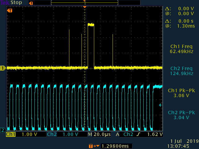
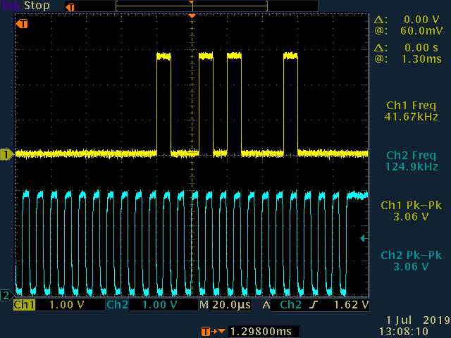
After digging deeper I found that if I program R57 to 0x0000 instead of the datasheet recommended value of 0x0020, everything worked well. With a value of 0x0020 the MISO data pulses were narrower when observed via a logic analyzer. The SPI on EK-TM4C123GXL is running at 125 kHz, just like on the Reference Pro. I can successfully run the SPI at maximum 1 MHz, most likely because of the sub-optimal connection via jumper wires.

I know that R57 is marked as reserved in the datasheet but I was hoping to find out more about this register and what it does.

Thanks,
Ayush

  • Hi Ayush,

    This is the first time I ever heard about this issue.

    The pulse width of the readback data should be equal to a SPI clock cycle. So it is 8ns for 125kHz CLK rate.

    Here is an example plot.

    With R57=0x20, the MUXOUT pin is able to drive as small as 50ohm load. That is why we made it as a default setting.

    Do you have a plot of the readback waveform to share?

  • Hi Noel,

    Thanks for responding so quickly. We have used LMX's in several products and never faced a problem which is why I was surprised as well.

    You are right, when I disconnected the logic analyzer the problem went away. I connected my oscilloscope with 1 Mohm probes instead and I can see runt pulses when the LA is connected to the test points. With just the microcontroller there are no issues. It appears that the logic analyzer leads distort the MISO waveform. I do not see a problem with other lines. Perhaps it has something to do with the load capacity setting through R57?

    Plots from my oscilloscope are attached. With logic analyzer - 

    Without logic analyzer -

    I have found the source of the problem with my prototype and I do not expect to have issues when the actual PCB gets made. Still, for the sake of learning, it would be great to know what the bits in R57 mean and any insight you have on the underlying cause of the problem would also be helpful.

    Thanks,
    Ayush

  • Hi Ayush,

    With logic analyzer, actually you've got some bits missing. I have no idea what went wrong.

    Like I said before, R57=0x20 has higher driving power than 0x00. This is the only thing R57 does.

  • Hi Noel,

    Thanks for the prompt help! I will mark this as resolved.

    Regards,
    Ayush