The TI E2E™ design support forums will undergo maintenance from July 11 to July 13. If you need design support during this time, open a new support request with our customer support center.

This thread has been locked.

If you have a related question, please click the "Ask a related question" button in the top right corner. The newly created question will be automatically linked to this question.

NE555: Issuse when IC turning back from Reset state

Part Number: NE555

Hi Guys,

I'm using an oscillator - NE555, And facing an issue when IC turning back from the reset state.

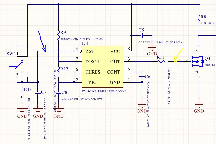
The issue is at the first time when turning back from resetting -> the IC keep at a high level for a long time more than the normal cycle (The cycle set by R9, R12,C8 - picture)

Could you help me explain what happened at this time (the times that IC turn back from reset)?

Is it a limiting by the IC or I controlled wrong something?

Here is the schematic and the capture of the Reset (Blue) and Output (Yellow) signal.

  • Hello Phuoc,

    A-stable mode on power up or after a reset will have an initial high time that is longer than expected. The reason is that the timing capacitor starts at 0V for first cycle and all remaining cycles start at 1/3 supply voltage.

    Here are two ways to "fix" this. Both work just as well for enable (reset going high) ; they work differently for preparation time during reset. The idea is to pull capacitor voltage to 1/3 VDD during reset low time. This works with all 555 timers including NE555.  

    Here is enable waveform (both circuits work fine)

    Here is the disable prep time (to get timing cap to 1/3 VCC)

    See how the top circuit , TC1, needs several seconds for capacitor voltage to get to 1/3 VCC

    See how the bottom circuit , TC2, only take a fraction of a second for capacitor voltage to get to 1/3 VCC

    Basically when the RB resistor between pins 6 & 7 is large resistance use the bottom circuit to force cap with lower impedance of R10 in parallel with R11. (R10 = 2* R11)

    Alternatively when the RB resistor between pins 6 & 7 is small resistance use the top circuit to force cap with R4 (set to 2*R2). 

  • Hi Ronald,

    This issue resolved, thank you very much.

    Phuoc (Mr.)