This thread has been locked.

If you have a related question, please click the "Ask a related question" button in the top right corner. The newly created question will be automatically linked to this question.

LMX2592: LMX2592 channel divider output wrong frequency

Part Number: LMX2592

Hi,Ti

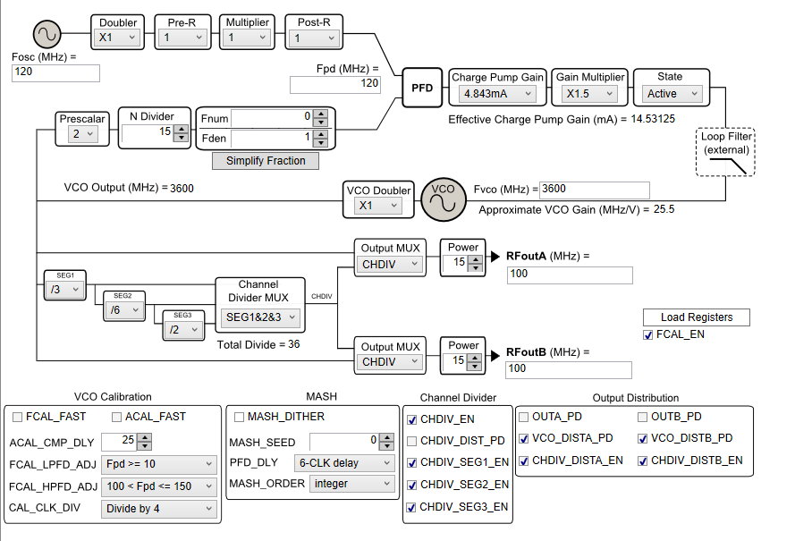
MY design  on the basis of  TICS;As show on the below: FVCO=3600m;VCO Doubler:X2;Total Divider is 72; Fosc=120M;Theoretically,RFoutA/RFoutB=100M,but,the result is 112M;

all the register configuration is conform to TICS;

Thank you  

  • Hello,

    please double check your Fosc input frequency and PLL is locked

    You can also enable the VCO output to bypass channel divider to observe VCO frequency.

    If you can attach your .tcs file this would be helpful.

    Regards,

  • Hi There,

    Couples of comment:

    Do not set the Gain Multiplier to 2.5x. We recommend at most 1.5x. 

    Set CAL_CLK_DIV to "Divide by 2" or "Divide by 4".

    To get 100MHz output, you don't need to double the VCO frequency. Try disable the VCO doubler and set SEG3=2.

  • Hello,

    Thanks for your help;

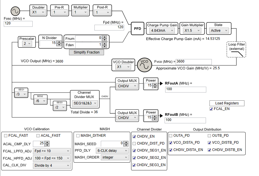
    According to your advice,We change the Value Gain Multiplier to 1.5x,Set "CAL_CLK_DIV " Divide by 4;

    The parameter is:

    1. Fosc=120M;

    2.FVCO=3600M;

    3.VCO Doubler:X1;

    4.Total Divider is 36;

    5.Theoretically,RFoutA/RFoutB=100M,

    As shown in the following figure,All the register configuration is conform to TICS.

    After testing,MUXOUT=3.3V,It indicates PLL is Locked;

    Using spectrograph verified the VCO=3600M;

    But, the RFoutA/RFoutB=150M  which is detected by  spectrograph.

    Please help me out of my confusion!

    Thanks

  • Hello,

    Thanks for your help;

    According to your advice,We change the Value Gain Multiplier to 1.5x,Set "CAL_CLK_DIV " Divide by 4;

    The parameter is:

    1. Fosc=120M;

    2.FVCO=3600M;

    3.VCO Doubler:X1;

    4.Total Divider is 36;

    5.Theoretically,RFoutA/RFoutB=100M,

    As shown in the following figure,All the register configuration is conform to TICS.

    After testing,MUXOUT=3.3V,It indicates PLL is Locked;

    Using spectrograph verified the VCO=3600M;

    But, the RFoutA/RFoutB=150M  which is detected by  spectrograph.

    Please help me out of my confusion!

  • Hi There,

    I verified your configuration with an EVM, I don't have your issue, I can get exact 100MHz signal from both RF outputs.

    Couples of suggestion:

    Use TICS Pro to generate all the register settings. You can export all the register values in a text file and use it in your software.

    Make sure that after the first Vcc power up, you need to program all registers in reverse order. That is, from R64 to R0.

    Use a scope to view the signals.