This thread has been locked.

If you have a related question, please click the "Ask a related question" button in the top right corner. The newly created question will be automatically linked to this question.

LMK04803: Phase detector frequency and Loop bandwidth design

Guru 19785 points
Part Number: LMK04803


Hi Team,

There is following description in LMK04803 datasheet page 115.

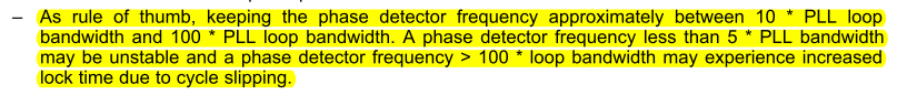
When I simulated design and phase noise using WEBENCH Clock Architect, the design was not following this guideline.

I believe there are many cases that could not meet the above recommendation.
Does the device still operate normally when not meeting this condition, besides having the longer lock time ?

It would be helpful if you could advise us the best setting for the below requirements based on the TICS-Pro.

- Input : 27MHz
-Output : 27MHz (LVDS), 75MHz (LVCMOS)

Best Regards,
Kawai

  • Hi Team,

    Could anybody help us ?

    Best Regards,

    Kawai

  • Hello Kawai,

    Assuming the input to PLL2 is 27 MHz, the phase detector can also be 27 MHz and the VCO frequency can be set to 2025 MHz (prescaler of 5 and N-divider of 15). The channel output dividers can be 75 (yields 27 MHz LVDS) and 27 (yields 75 MHz LVCMOS).

    A 27 MHz phase detector frequency should work well with a loop bandwidth of between 250kHz and 300kHz. I recommend using PLLatinumSim software to generate component value recommendations for the loop filter.

    Regards,

  • Hello Derek-san,

    Thanks for the comments.

    Q). As long as the PLL could get enough phase margin, can we use the loop BW and phase detector frequency which is out of this rule ?

    Q). In the below result, it seems PLL phase margin is only about 20 decrees. It seems it does not have enough phase margin. Does this really work ?

    - PDF = 27MHz
    - Loop BW = 272kHz

    Best Regards,

    Kawai

  • Hi Kawai-san,

    Q1) If the phase margin is large enough to be stable (>45° generally), it is acceptable to choose other loop bandwidth and phase detector values. Changing the phase detector frequency and loop bandwidth will affect the phase noise, so keep this in mind when making changes.

    Q2) The integrated loop filter components for the LMK04803 restrict the allowable values for R3/R4/C3/C4. The maximum achievable bandwidth I could find was about 215 kHz, which should be fine (phase margin of about 68°).

    Regards,

  • Hi Derek-san,

    Thanks for your comments.

    It seems I had the older software version that the tool couldn't simulate with the internal filter value restriction.

    I updated the software and tried again.
    Using the below filter value, I can read that there is over 60 degrees phase margin.

    However, I have one question.

    How can you read this from the bode plot graph ?
    I thought you would read the phase margin at the point where closed loop gain is 0dB.

    Best Regards,

    Kawai

  • Hi Kawai-san,

    From the PLL Performance, Simulation, and Design textbook:

    The loop bandwidth frequency is defined as the location where the loop gain is attenuated by half (about 3dB).

    Regards,

  • Hi Derek-san,

    I understood. Thanks for your kind support.

    Best Regards,

    Kawai