This thread has been locked.

If you have a related question, please click the "Ask a related question" button in the top right corner. The newly created question will be automatically linked to this question.

LMK05028: Output at the time Switchover

Part Number: LMK05028

Hello, 

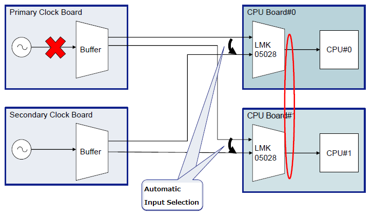
My customer is considering using the following configuration.

・ Even if one of the clock sources is lost, the LMK05028 is expected to switch to one of the clock sources by automatic input selection.
⇒ It is possible to switch.
• Expects the CPU to operate synchronously when switching occurs.
⇒ Whether or not to operate synchronously depends on the requirements of the customer's system.

[Q1]
Is the above usage assumed as a device?
I think the above usage is a special usage.

[Q2]
The customer expects the output frequency during a switch over event to be the same between devices.

Their idea is as follows.
If the input to the same PLL IC is switched to the same Reference Clock, the behavior of the PLL IC is the same.
That is, the output fluctuation is the same.

I believe that the following factors contribute to variations in PLL operation.
・ KPD
・ Z (s)
・ KVCO
・ Initial state of input
I think LMK05028 is DPLL, so there is no variation in KPD Z (s) KVCO.
In that case, I think that there is a reason for the customer.

However, the initial state variation is an external factor and needs to be evaluated by the customer.

There is no spec that characterizes the fluctuation of output at the time of switchover.


Is my understanding correct?
Please tell me if you have any questions.

Best Regards,

Kaede Kudo

  • Hello Kudo-san,

    KAEDE KUDO said:
    [Q1]Is the above usage assumed as a device?

    This appears similar to a line card application in which two timing cards are providing references to several line cards in a system.  If one timing card goes down, then the LMK05028 can switch over to the second timing card.  This is a common use case.  Please refer to the application note snaa315, ITU-T G.8262 Compliance Test Results for the LMK05028 Digital PLL Network

    Section 6 highlights Phase Transient Generation.  Figure 25 shows that the phase transient upon a switch is effectively 0.  As with Figure 29 and 30.  Section 7 contains Figure 34 and 35 showing phase transient in holdover.  Finally Section11, appendix, shows both phase and frequency transient caused during a switch as measured on an E5052.

    KAEDE KUDO said:
    [Q2]The customer expects the output frequency during a switch over event to be the same between devices.


    Yes, I expect the frequency to remain the same.

    73,
    Timothy

  • Hello Timothy-san,

    Thank you for your reply。

    In G.8262, if the G.8262 standard is satisfied, the system will not go down even if the inputs of multiple LMK05028s are switched simultaneously.
    In other words, I understood that it can be used without problems if the customer's system requirements are the same or looser than G.8262.

    Is my understanding correct?

    Best Regards,

    Kaede Kudo

  • Hello Kudo-san,

    That is correct.

    73,
    Timothy

  • Timothy-san,

    Thabk you for your reply.

    I understood your answer.

    Best Regards,

    Kaede Kudo